


11
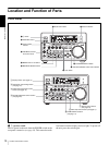
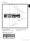
Location and Function of Parts
Chapter 1 Overview
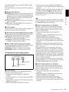
b SC (subcarrier phase)/SYNC (synchronization
phase) control
Turn the SC control to accurately adjust the subcarrier
phase of the composite video output signal of the unit with
respect to the reference video signal.
c Control mode selector
Selects whether the unit is operated from its front panel or
from external equipment.
KEY INHI (key inhibit): All controls in the recording/
playback control section and the search control section
are disabled. In this state, the unit cannot be operated
from its front panel or from a remote control unit
connected to the CONTROL connector.
LOCAL: The unit is operated from its front panel or from
an RM-LG2 Remote Control Unit (supplied)
connected to the CONTROL connector.
REMOTE: The unit is operated from external equipment
connected to the REMOTE IN (R)/OUT (P)connectors
or S400(i.LINK) connector on the rear panel.
Select which of the connectors to use with the
REMOTE I/F menu item (see page 69).
Note
When you edit using the S400(i.LINK) connector,
with video and audio signal input set to i.LINK (see
page 15) and remote control set to 9PIN (see page 69),
the locations where edit points are actually set may not
be the same as the specified locations.
When you set video and audio signal input to i.LINK,
set remote control to i.LINK as well.
d PHONES connector (stereo phone jack) and
control knob
Connect stereo headphones to the connector for audio
monitoring during recording or playback. The control
knob controls the volume of the headphones. It also
controls the level of the audio signal output from the
MONITOR connector on the rear panel.
The settings made with the METER CH-1/2 3/4 button and
MONITOR SELECT button select the audio channels for
audio output via this connector. The same channel
selection as for the audio level meters applies to this
connector.
e METER CH-1/2 3/4 button
Pressing this button toggles the audio level meter mode
between CH-1/2 (channels 1 and 2) and CH-3/4 (channels
3 and 4).
The settings made with this button and the MONITOR
SELECT button select the channels for level indications
and audio output.
For more details, see “6 MONITOR SELECT button.”
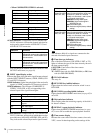
f MONITOR SELECT button
Use this button and the METER CH-1/2 3/4 button to
select the audio channels:
• for level indications on the audio level meters
• for audio output via the PHONES connector on the front
panel
• for audio output via the MONITOR connector on the
rear panel
Depending on the setting made with the METER CH-1/2
3/4 button, the channels for output to the above meters and
connectors are selected as follows.
When CH-1/2 mode is selected with the METER CH-1/
2 3/4 button:
When CH-3/4 mode is selected with the METER CH-1/
2 3/4 button:
g CLIP button
This button is used for setting up and modifying clip lists,
and for clip segment playback operations.
See Chapter 4 for details about clip operations.
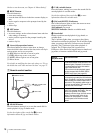
h LINE OUT SELECT button and indicators
When you are recording and playing back at the same time,
use this button to select output of playback or recording
signals. Each press of the button selects the other signals.
Recording signals are output when the R indicator is lit.
Playback signals are output when the P indicator is lit.
When the R indicator is lit: Recording signals are output.
When the P indicator is lit: Playback signals are output.
When both indicators are lit: Output signals are
recording signals or playback signals, as selected by
the R button and the P button in the PANEL SELECT
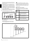
Audio level meters PHONES
connector
MONITOR
connector
CH-1 (channel 1) only.
Only the left meter lights.
Channel 1 only
(monaural)
Channel 1 only
CH-2 (channel 2) only.
Only the right meter
lights.
Channel 2 only
(monaural)
Channel 2 only
CH-1 and CH-2 (channels
1 and 2).
Both the left and right
meters light.
Channels 1
and 2 (stereo)
Channels 1
and 2 (mixed)
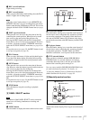
Audio level meters PHONES
connector
MONITOR
connector
CH-3 (channel 3) only.
Only the left meter lights.
Channel 3 only
(monaural)
Channel 3 only
CH-4 (channel 4) only.
Only the right meter
lights.
Channel 4 only
(monaural)
Channel 4 only
CH-3 and CH-4 (channels
3 and 4).
Both the left and right
meters light.
Channels 3
and 4 (stereo)
Channels 3
and 4 (mixed)