


69
Menu Contents
Chapter 6 Menu Setting
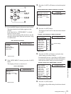
INT AUDIO SG [> Audio SG]: Select the operation of the
internal audio test signal generator.
SILENCE [>> silence]: Silent signal
*1kHz SINE [>> 1kHz]: 1-kHz, −20 dB FS (for DSR-
DR1000A) or −18 dB FS (for DSR-DR1000AP) sine wave
signal
When you select SG (audio test signal) as the audio input in
the video/audio input setting section on the front panel, the
audio test signal generated by the internal audio test signal
generator is input.
JOG CONTROL [> Jog ctrl]: Select whether to adjust the
audio playback speed during slow playback.
OFF [>> OFF]: Do not adjust the audio playback speed.
*ON [>> ON]: Adjust the audio playback speed.
SHUTTLE MUTE [> Shutl mute]: Set the audio muting
conditions during shuttle playback.
*OFF [>> OFF]: Not muted.
CUEUP or PREROLL [>> CUEUP]: Muted during cue-up or
preroll operations.
FULL [>> FULL]: Muted in shuttle mode.
DV ATT [> DV PB ATT]: When playing back a clip recorded in
consumer DV format, select whether to attenuate the audio
output level.
OFF [>> OFF]: Do not attenuate.
*ON [>> ON]: Attenuate.
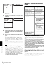
INTERFACE SELECT [Interface]: Settings related to
external interfaces
Description of settings
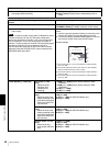
VIDEO OUTPUT [> Video Out]: Select the four format of
analog video signals to be output from the four VIDEO
OUT connectors (Y/CPST, R−Y/S−C, B−Y/S−C and
SUPER).
Note
When this menu item is set to Y−R, B, the SUPER connector
outputs the B−Y signal. In this case, changing the setting of an
internal switch allows the text data for superimposition on the
monitor screen to be output from the right-hand REF. VIDEO IN
connector (marked ). For more information about this,
consult your Sony dealer.
*COMPOSITE [>> Composite]: Composite video signals
S-VIDEO [>> S-Video]: S-video (separated Y and C) and
composite video signals
Y–R, B [>> Y–R, B]: Y, R−Y and B−Y component video
signals
AUDIO OUTPUT [> Audio Out]: Select the channels for audio
output from the AUDIO OUT 1/3 and 2/4 connectors.
*1/2 CH [>> 1/2CH]: Output channel 1 to the AUDIO OUT 1/3
connector and channel 2 to the AUDIO OUT 2/4
connector.
3/4 CH [>> 3/4CH]: Output channel 3 to the AUDIO OUT 1/3
connector and channel 4 to the AUDIO OUT 2/4
connector.
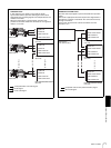
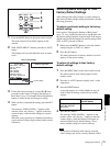
REMOTE I/F [> Remote I/F]: When remote-controlling this unit
with the control mode selector set to REMOTE, select
either the REMOTE IN (R)/OUT (P) connector or
S400(i.LINK) connector for connecting a remote control
unit.
i.LINK [>>i.LINK]: Device connected to S400(i.LINK)
connector.
*9PIN [>>9PIN]: Device connected to REMOTE IN(R)
connector. Do not use REMOTE OUT(P) connector.
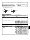
9PIN(PARA) [>>9P Para]: Make cascade connection
between multiple units of this recorder using the REMOTE
IN(R) and REMOTE OUT(P) connectors, controlling all
recorders remotely from one recorder.
9PIN(DUAL) [>>9P Dual] : Control recording remotely from
device connected to REMOTE IN(R) connector. Control
playback remotely from device connected to REMOTE
OUT(P) connector.
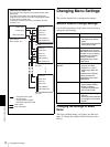
PC REMOTE [>PC REMOTE]: Select whether or not to enable
control from a computer
*DISABLE [>>DISABLE]: Disable.
ENABLE[>ENABLE]: Enable.
AUDIO CONTROL [Audio]: Settings related to audio
control
Description of settings