


Chapter 2 Names and Functions of Parts
13
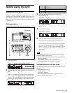
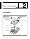
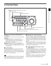
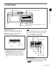
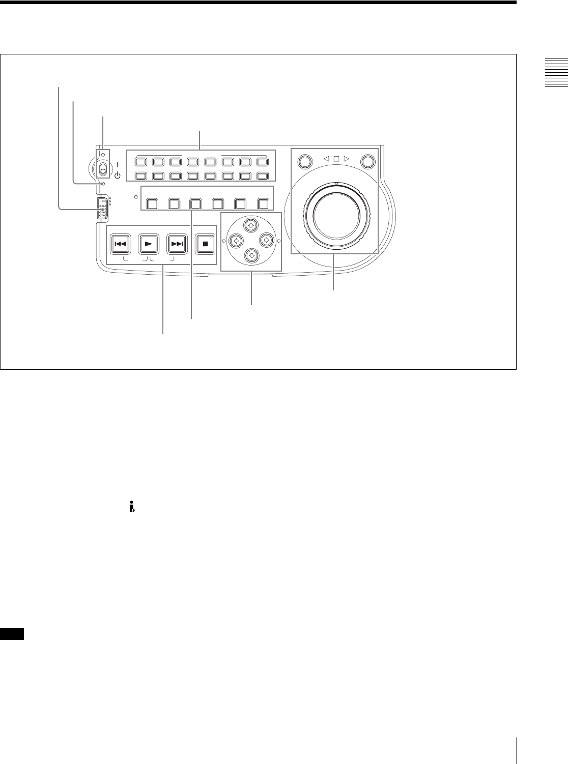
2-2 Control Panel
2-2 Control Panel
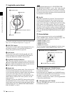
a Remote control switch and NETWORK access
indicator
Different positions of the switch allow different operations
as follows.
NETWORK: Enables access to the network. The
indicator lights when an external network device is
being accessed. In this state, operation from the
control panel is not possible.
LOCAL: Enables operation from the control panel.
REMOTE: Enables remote control of the PDW-V1 from
a device connected to the S400 (i.LINK) connector
on the side panel.
b ACCESS indicator
This lights when the disc is accessed and when a file is
opened by a FAM or FTP connections (see page 56).
If the on/standby switch is set to the 1 position while this
indicator is lit, access to the disc is completed before the
unit switches to the standby state.
Note
While the ACCESS indicator is lit, do not turn off the AC
power switch, disconnect the power cord, or remove the
battery. This could lead to a loss of data from the disc.
c On/standby ("/
1) switch and indicator
When the AC power switch on the rear panel is in the "
position, or a battery is loaded, this switches the PDW-V1
between the operating (") and standby (1) states. When
the switch is moved to the " position, the indicator lights.
When the switch is moved to the 1 position, the indicator
goes off.
When operating the PDW-V1 from an AC power supply,
normally leave the AC power switch in the " position, and
switch the PDW-V1 between the operating and standby
states using the on/standby switch.
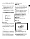
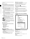
d AUDIO MONITOR (audio monitor channel
selection) buttons
Each of the L (upper) and R (lower) rows has buttons CH-
1 to CH-8 corresponding to channels 1 to 8. When a button
is pressed, it lights, and the corresponding audio channel is
output from the PHONES jack and speaker on the front
panel and AUDIO MONITOR OUT L/R connectors on the
side panel.
In each of the L and R rows, if the buttons for more than
one channel are selected simultaneously, the selected
channels are mixed on the audio monitor output.
ACCESS
L
R
NETWORK
LOCAL
REMOTE
AUDIO MONITOR
CH-1 CH-2 CH-3 CH-4 CH-5 CH-6 CH-7 CH-8
SHUTTLE JOG
THUMBNAIL
ESSENCE
MARK
MARK1
MARK2
IN
OUT
MENU
S.SEL
SET
RESET SHIFT
TOP F REV F FWD END
PREV NEXTPLAY STOP
CLIP
MENU
SYSTEM
MENU
SUBCLIP
3 On/standby switch and indicator
4 AUDIO MONITOR buttons
2 ACCESS indicator
1 Remote control switch and NETWORK access indicator
1 Jog/shuttle control block (see page 14)
3 Operating mode selection/menu setting section (see page 15)
4 Playback controls (see page 15)
2 Arrow buttons(see page 14)