


Chapter 3 Preparations
25
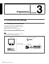
3-1 Connections and Settings
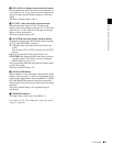
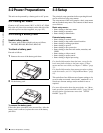
3-1-3 Connecting to a Nonlinear Editing System
You can send video/audio signals (AV/C data) from this
unit to a nonlinear editing system connected to the S400
(i.LINK) connector.
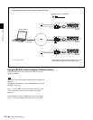
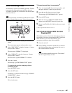
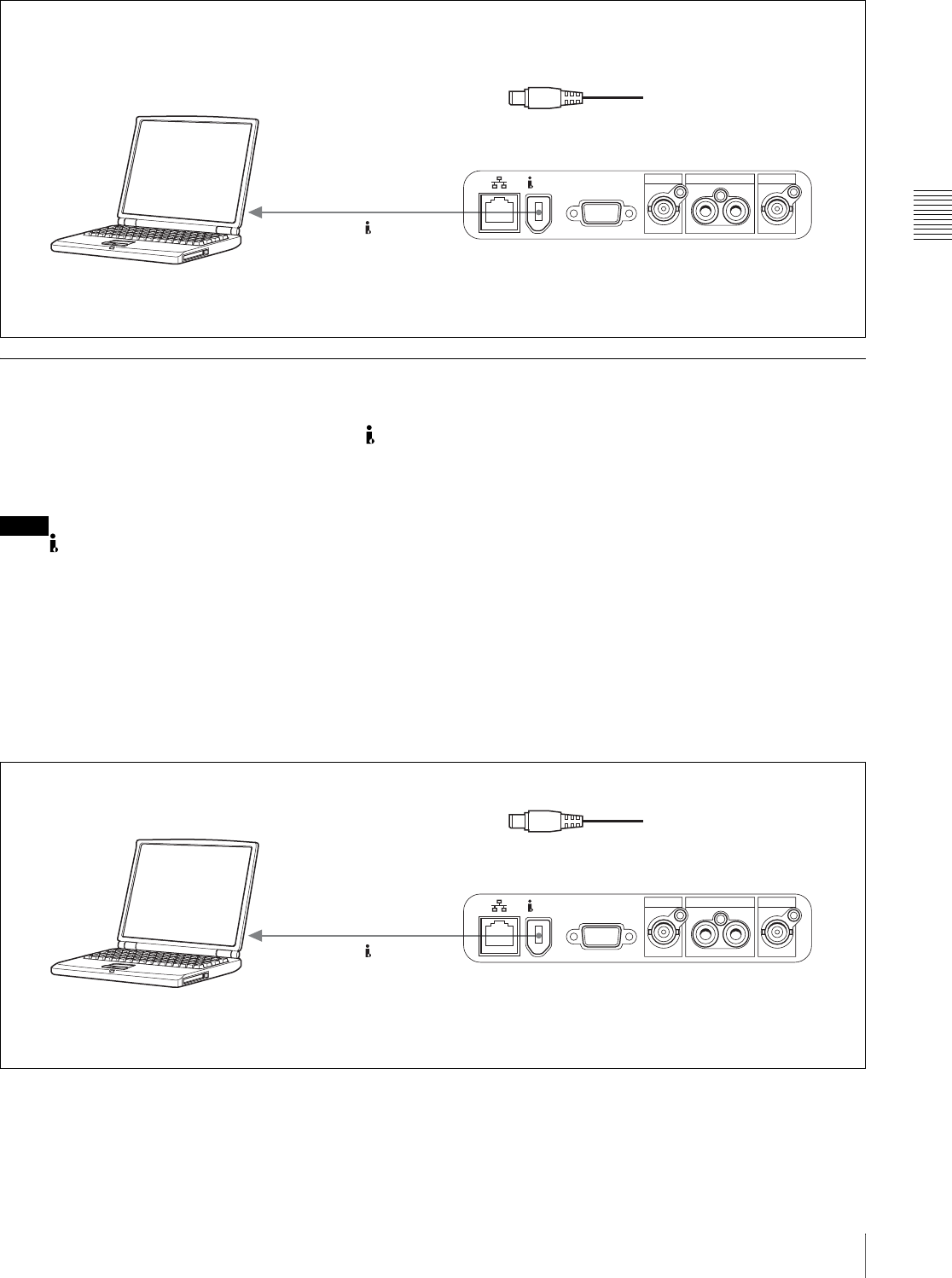
The following figure shows an example connection.
Notes
• The S400 (i.LINK) connector of this unit outputs
video/audio signals in DVCAM format. Data recorded in
MPEG IMX format is output after being converted into
DVCAM format.
• The nonlinear editing system to be used being connected
to this unit requires editing software (not supplied)
supporting DVCAM format.
• Make the following settings before transferring video/
audio signals (AV/C data) from this unit to a nonlinear
editing system.
Audio mode selection
Use extended menu item 831 “DV OUT AUDIO
MODE” to select either of the following.
4ch: 12 bit/32 kHz/4 ch
2ch: 16 bit/48 kHz/2 ch (Factory default setting)
Audio output channel selection
Select the audio output channels with extended menu
item 828 “SDI/DV AUDIO OUTPUT SELECT.”
For information about how to make extended menu item
settings, see 7-3-2 “Extended Menu Operations” on
page 82.
For the method of transferring video/audio signals (AV/C
data) to a nonlinear editing system, refer to the manual
provided with the editing software to be used.
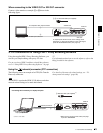
VIDEO OUT
MONITOR
SDI OUT
AUDIO MONITOR OUT
LR
S400
1
PDW-V1
S400 (i.LINK)
1: i.LINK cable (not supplied)
To i.LINK (IEEE1394)
connector
Laptop computer
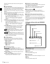
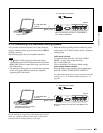
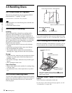
Make sure extended menu item 215 “i.LINK MODE” is
set to “FAM (PC REMOTE).”
VIDEO OUT
MONITOR
SDI OUT
AUDIO MONITOR OUT
LR
S400
1
PDW-V1
S400 (i.LINK)
1: i.LINK cable (not supplied)
To i.LINK(IEEE1394)
connector
Laptop computer
(With editing software supporting
DVCAM format installed)
Make sure extended menu item 215 “i.LINK MODE” is set
to “AV/C.”