2-76
Section 2 — Installation
System Timing (13.5 MHz, Serial I/O only)
The Model 2200 switcher has timing compensation to adjust an analog
reference signal not in time with the serial inputs. The controls may also
offset the position of the serial inputs within the timing window to
minimize the delay through the switcher, for example. Timing is adjusted
with the FINE, MEDIUM and COARSE rotary switches on the front of the
064801 Sync Generator Module located in Slot A9 in the top of the front A
Bay of the switcher frame.
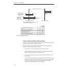
These controls move the timing of the whole switcher - the output timing
and the input timing window - relative to the analog reference to the
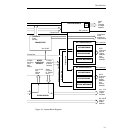
switcher. Refer to Figure 2-40 for a timing diagram of the timing ranges.
The range of each control is as follows:
■ FINE: 296 ns total (18.5 ns per step)
■ MEDIUM: 4.74 µS total (296 ns per step)
■ COARSE: 75.8 µS total (4.74 µs per step)
Set the controls to the nominal center shown below:
■ FINE = 0
■ MEDIUM= 0
■ COARSE = 8
Equipment Required
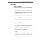
■ A signal source with a black-to-white transition in active video for use
as a timing reference (for example, Pulse and Bar).
■ A non-timing serial digital analog converter. (The timing of the analog
video is directly related to the timing of the serial input).
■ A wide-band oscilloscope with a delayed sweep, externally locked to a
house reference.


