


Operating Instruction Book
TU-HDT104A
7
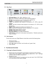
4 Installing Your Digital Receiver
4.1 Connecting Your Digital Receiver
The following illustrations show some examples for connecting this HD Digital
Receiver. Select the connection that is best suited for your needs. Many other
connections may be possible when optional devices such as RF cable splitters are
included in your system. These devices may cause signal degradation and, if too
many are used, poor quality picture and sound may result.
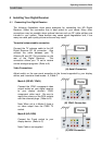
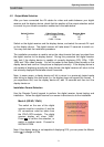
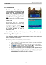
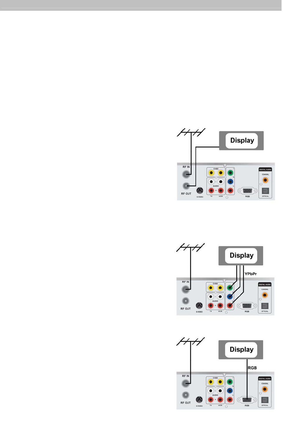
Terrestrial antenna/cable connection
Connect the TV antenna cable to the HD
Digital Receiver RF IN connector. Also
connect the cable between your TV
Antenna IN and RF Out connector on the
rear of the Digital Receiver. This
connection allows your TV set to receive
normal analogue programs. (Refer to A)
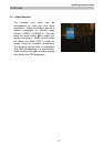
Video Connections
Adjust switch on the rear panel according to the format supported by your display
device, and it contains three modes: A, B and C
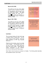
Mode A (SD/HD, YPbPr)
Connect the YPbPr component video
output socket on your digital receiver
to your display device’s YPbPr
component video input. Be sure to
match the colours on the RCA sockets
with the coloured plugs. (Refer to B)
Note: When unit is in Mode A, there is
no video output from the CVBS TV
socket.
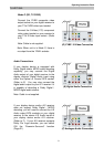
Mode B (HD, RGB)
Connect the D-sub socket to your
display device. (Refer to C)
Note: Cable is not supplied.
(A) Aerial Connection
(B) YPbPr Connection
(C) RGB Connection