F-IN-D Series
Electromagnetic Flowmeter for
Partially-filled Pipes
LF502
150
to
600
mm
(
6
”
to
24
”
)
EJL-
064A
Introduction
The LF502 electromagnetic flowmeter uses Faraday’s
Law of electromagnetic induction in the same way as
conventional electromagnetic flowmeters to measure
the flow rate. Position of electrodes in the LF502 is so
designed that it can be used even in a partially-filled
pipe to measure the flow rate.
Improved functional magnetic field distribution tech-
nique enables a high-precision flow measurement con-
tinually from low-level to fully-filled flow conditions.
This
eliminates
unnecessary
piping
work
such
as
lifting
the downstream pipe section to fill the detector pipe.
Compared with flowmeters measuring the flow rate by
means of flow level, the obstructionless LF502 flow-
meter does not usually allow mud, sands and other
solid sediment stay at the bottom of the detector pipe
and
is
unaffected
by
wave
or
floating
solids
on
the
fluid
surface.
The
AF100
hand-held
terminal
or
the
Model
275
HART
communicator can be used to communicate with the
flowmeter
from
remote places using the HART com-
munications protocol. See the communications output
specifications for details about the HART protocol.
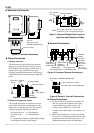
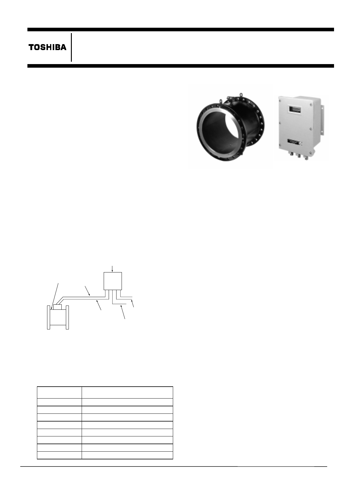
Figure
1. LF502 Configuration
Specifications
„
Overall Specifications
Measurement range:
Meter size
in mm (inch)
Measurement range
150 mm (6”)
0 –
60 m
3
/h (std) to 0 –
300m
3
/h
200 mm (8”)
0 – 110 m
3
/h (std) to 0 – 550m
3
/h
250 mm (10”)
0 – 175 m
3
/h (std) to 0 – 875m
3
/h
300 mm (12”)
0 – 250 m
3
/h (std) to 0 –1250m
3
/h
350 mm (14”)
0 – 350 m
3
/h (std) to 0 –1750m
3
/h
400 mm (16”)
0 – 450 m
3
/h (std) to 0 –2250m
3
/h
500 mm (20”)
0 – 710 m
3
/h (std) to 0 –3550m
3
/h
600 mm (24”)
0 –1000 m
3
/h (std) to 0 –5000m
3
/h
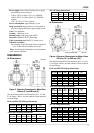
Figure 2. LF502 Electromagnetic Flowmeter
for Partially-filled Pipes
Fluid-level range:
x
30 mm (1 1/4”) to fully-filled condition for Meter
sizes 150 mm (6”) to 300 mm (12”)
x
10%
of
inside
tube
diameter
to
fully-filled
condition
for Meter sizes 350 mm (14”) to 600 mm(24”)
Accuracy:
±2 % FS (when measurement range is
standard)
Note:
The accuracy is measured under standard
operating
conditions
at
Toshiba's
calibration
facility.
Required straight pipe length:
10D
minimum on upstream side and
5D minimum on downstream side
Note:
D is a nominal meter size.
Fluid conductivity:
100µS/cm minimum
Fluid temperature:
0 to 55 °C (32 to 131 °F)
Ambient
temperature:
–10 to 50 °C (14 to 122 °F)
„
Detector Specifications
Meter sizes:
150 mm (6”), 200 mm (8”), 250 mm
(10”), 300 mm (12”), 350 mm (14”), 400 mm
(16”), 500 mm (20”), and 600 mm (24”)
Fluid pressure:
0
to 2.0 MPa under fully-filled fluid
condition for flange-connected flowmeters
Connection flange standards:
ANSI 150, BS 16,
DIN PN16 and others.
Structure:
NEMA 4 (IP 67) Watertight (standard),
NEMA 6 (IP 68) Submersible
(option)
Coating:
Phthalic acid resin coating, pearl-gray colored
(standard for watertight type) or black tar epoxy
(option for watertight type and specified
exclusively for submersible type)
Detector
Signal cable
Converter
Excitation
cable
Digital I/O
Power supply
4-20 mA dc