TIC-LF414C
Introduction
The electromagnetic flowmeter uses Faraday’s Law of
electromagnetic induction to measure the process flow.
The device consists of two units: a detector, through
which the fluid to be measured flows and in which
low-level signals proportional to flow rates are
obtained; and a converter, which supplies excitation
current to the detector, and amplifies the signals from
the detector and then processes and converts the signals
into the 4–20mAdc current signal or communication
signal. With the unique patented Mount- Anywhere
magnetic field distribution technology, the meter is
highly immune to upstream flow disturbances.
Combined with a multi-functional converter LF610
(combined type) or LF612 (separate type) equipped
with its patented Noise-Sentry original noise-
suppression circuit and advanced algorithms. The
LF410 has a very high tolerance to noise, giving the
unit a very stable output even for slurry fluid
measurement. IR (Infrared) switches enable parameter
setting of the converter without removing the cover.
Flow direction can be set in either way, and its unique
128 x 128 dot matrix LCD display allows the LCD to
be rotated electronically to 90, 180 and 270 degrees
without opening the cover.
The AF900 hand-held terminal (HART*
1
communicator) can be used to communicate with the
flowmeter from a remote place. PROFIBUS-PA*
2
interface is available as an option.
*1: HART protocol (Highway Addressable Remote
Transducer) is a communication protocol for industrial
sensors recommended by the HCF
(HART
Communication Foundation).
*2: PROFIBUS is the communication protocol for factory
and process automation that the PROFIBUS
Organization recommends. Instead of analog control
with a conventional analog signal (4-20mA), it is
fieldbus which digitizes all signals. Flowmeters support
PROFIBUS-PA.
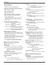
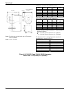
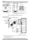
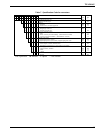
Power
supply
Converter
I/O
Detector
Combined type
LF410/LF610
LF414/LF610F
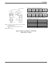
Converter
Power
supply
Signal cable
Detector
Separate type
LF410/LF612
LF414/LF612F
Terminal box
I/O
Figure1. Configuration
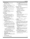
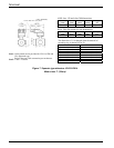
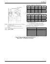
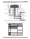
LF410/LF610 LF410 LF612
LF414/LF610F LF414 LF612F
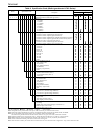
Figure2. LF410 Mount-Anywhere series
Flowmeters
Specifications
Overall Specifications
Measurement range in terms of flow velocity:
0
–1.0 ft/s to 0 – 32.8 ft/s (0 – 0.3 m/s to 0 –10 m/s).
0
– 0.3 ft/s to 0 – 1.0 ft/s (0 – 0.1 m/s to 0 – 0.3 m/s)
range is available optionally.
Accuracy:
±0.2 % of Rate*
* This pulse output error result is established under standard
operating conditions at Toshiba's flow calibration facility,
Fuchu Japan. (NIST Traceable).
* Individual meter measurement error may vary up to ±0.5% of
Rate at 1.64ft/s (0.5m/s) or more and ±0.3% of rate ±0.039
inch/s (1mm/s) at 1.64 ft/s (0.5 m/s) or less.
* Current output: plus ± 8µA (0.05% of span.)
* Refer to individual calibration data for each individual meter's
measurement error.
Fluid conductivity: 5µS/cm minimum
Fluid temperature:
14 to 356 °F (–10 to +180°C) : Ceramic type
Note : 248°F (120°C) above is separate type
14 to 248°F (–10 to +120°C) : Teflon PFA
Ambient temperature:
-
4 to 140 °F (
-
20 to + 60 °C)
Structure: IP 67 and NEMA 4X Watertight
Field Intelligent Device – Mount-Anywhere Series - Wafer
Electromagnetic Flowmeter
LF414 /LF610
LF414 /LF612
1/2" to 8" (15 to 200 mm)
Certification number
Z01207