MODEL
48195D
Dinky Link™ Surface Mount
Universal IR Receiver
INSTALLATION INSTRUCTIONS
DESCRIPTION
These small IR receivers have been designed for mounting in very small
spaces. They may be mounted under shelf edges, cabinet ledges, in wall
speakers, etc. – anywhere an inconspicuous appearance is desired. The
high sensitivity of these receivers allows placement behind speaker grilles
and still receive IR commands up to 100 feet away*.
FEATURES
Wire channel for clean installation.
System testing red-talk-back LED.
Includes 3-Terminal Block for easy extension to remote room locations.
SPECIFICATIONS
Infrared carrier frequency bandwidth: 25 - 100kHz.
Reception range: Up to 100 feet.*
Reception angle: +/- 60 degrees.
Cable requirements: See “INSTALLATION” below.
Max. transmission length: 1 mile using 18 gauge wire.
Maximum current output: 100mA
Drives IR emitters through Xantech Connecting Blocks, Controllers, etc.
Dimensions: 2.55” x 0.55” x 0.35” (65mm x 14mm x 9mm)
Power requirements: +12VDC, 20mA.
Depending on remote control output strength and ambient conditions.
MOUNTING
The IR receiver can be mounted to any flat surface, using the two-sided
adhesive tape supplied. Two screws are included for mounting the 3-terminal
block provided with the IR receiver.
An additional feature is a wire channel on the rear of the surface mount IR
receiver. This will give the installer the ability to provide clean wire dressing
in any direction.
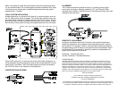
INSTALLATION
QUICK-START
A typical system will use an IR receiver, several emitters, and a power supply
all connected to a connecting block.
1. Connect the IR receiver to the “IR RCVR” port on the connecting
block. The ‘red’ connector is installed to the ‘red’ plug.
Note: In some extended distances, additional 3-conductor may be required and can
be connected to the terminals on the connecting block.
2. Connect the Emitters to the connecting block. The ‘yellow’ connector
is installed to the ‘yellow’ plug.
3. Connect the power supply to the connecting block.
4. Installation complete
REMOTE ROOM APPLICATION
One application is to locate the IR receiver in a remote room. This will give
the end-user the ability to control audio/video equipment from a location
where the remote control no longer has the ability of direct line-of-sight.
The IR receiver will need the 3.5mm stereo type mini plug removed to extend
the wire run to the connecting block. A 3-terminal block is supplied to connect
the IR receiver to the connecting block with a 3-conductor inter-room cable in
between.
The 3-conductor inter-room cable (24 gauge up to 200’, 22 gauge up to 600’,
20 gauge up to 2000’, 18 gauge up to 5000’), is run to the main room.
Input connections must be made as illustrated. To extend the emitter wires to
a more distant location, you may splice in 2-conductor wire, in the wire
gauges mentioned before, as needed.