1
Controllers
INSTALLATION INSTRUCTIONS
590-00
PROGRAMMABLE CONTROLLER
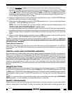
FRONT PANEL
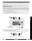
The front panel of the 590 is made of acrylic plastic. It should be cleaned with a soft cloth as it scratches
easily. Behind the panel are five red LEDs and an infrared sensor.
RED LEDs
ERROR - Lights when an error occurs in the learning process or when trying to send an
unprogrammed command.
PROGRAM - Lights when the PGM (program) button on the rear panel is pressed.
CONFIRM - Lights after a command has been memorized during programming.
DELETE - Blinks on and off when the DELETE button on the rear panel is pressed.
OUTPUT - Lights to indicate when infrared commands are being sent in response to a contact
closure. Contact closure is the most common form of input to the 590. If other types of inputs are
used, they will perform the same function as contact closures.
INFRARED SENSOR
Receives IR commands for programming the 590. It is located about one-half inch above the OUTPUT lamp.
1
12VDC
12VDC
1234
BANK
RES DEL SEQ PGM
+
–
2 3 4 5 6 7 8 9 10 11 14 15 16 O G – +12 13
ON
1234
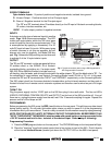
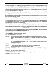
REAR PANEL
The following connectors, push-buttons and controls are located on the rear panel:
12VDC jack – the power supply plugs in here (center conductor is positive).
BUTTONS (Recessed - press with a pencil point or narrow blade screw driver).
RES - Reset - erases all stored commands.
DEL - Delete - allows erasure of selected commands.
SEQ - Sequence - begins and ends sequence mode programming.
PGM - Program - begins and ends learning mode.
BANK - Bank DIP Switch – Selects one of four memory banks on microprocessor.
CONFIRM
DELETE
PROGRAMMABLE CONTROLLER
PROG
RAM
ERROR
O
UTPUT
590
Infrared Sensor