23
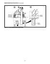
CASE SEALER FRAME
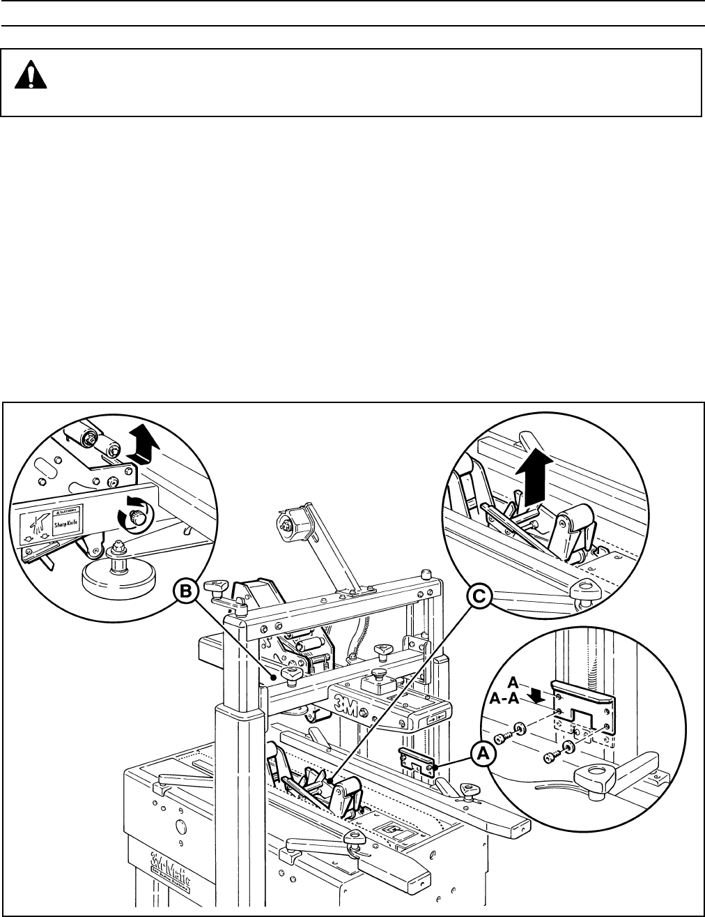
(Refer to Figure 6-1A)
1. Raise the upper head assembly by turning crank handle counterclockwise. Remove and retain the two stop
bracket screws and washers from the normal position holes "A-A".
2. Move stop bracket down and secure with original fasteners through upper holes "A" in stop bracket. Relocate
both right and left stop brackets.
The following changes to the case sealer frame and upper/lower taping heads will allow the taping of boxes
90 mm [3.5 inch] minimum height.
Changing the Tape Leg Length
(From 70 to 50 mm [2-3/4 to 2 inch])
WARNING Turn off electrical power and disconnect power cord from electrical supply before
beginning Special Set-Up Procedure. If power cord is not disconnected, severe injury to
personnel could result.
Special Set-Up Procedure
Figure 6-1 Case Sealer Frame Changes


