


12 78-8113-5098-8 Rev F
Instructions for UniShield
®
Shielded Cable
12.0 Prepare Cable
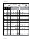
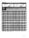
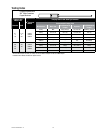
12.1 Check to be sure cable size fits within kit range as shown in Table 1.
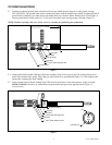
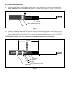
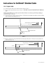
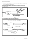
12.2 Prepare cable using dimensions shown in Figure 15. BE SURE TO ALLOW FOR DEPTH OF TERMINAL
LUG.
NOTE: Provide additional 1/4" (6 mm) exposed conductor distance to account for growth during crimping of
ALUMINUM lugs or connectors.
12.3 Install constant force spring as shown in Figure 15. Pull shield wires through semi-conductive jacket to leading
edge of constant force spring (Figure 15).
5 3/4" (146 mm)
Semi-Conductive Jacket
Constant Force Spring
Shield Wires
Depth Of Terminal Lug + Growth Allowance
Figure 15
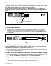
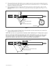
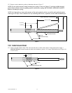
12.4 Remove constant force spring. Bend shield wires back upon cable jacket 1" (25 mm). Cut excess shield wire
and discard (Figure 16).
6 3/4" (171 mm)
1" (25 mm)
Semi-Conductive Jacket
Fold Back Shield Wires
Depth Of Terminal Lug + Growth Allowance
Figure 16