


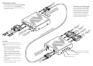

Video
input
from
PC
Optional
output
to
local
video
monitor
Power
input
CATx
link
connections
to
receivers
2, 3
and
4
(AV104
models
only)
Audio
input
from
PC
Optional
output
to
local
speakers
CATx
link
up
to
300m
(
1000
feet)
Audio
output
to
speakers
Audio
output
to
speakers
Video
output
to
display
V
ideo
output
to
display
Power
input
Optional
link
output
to
a
cascaded
receiver
(AV101
models
only)
TRANSMITTER
LINK
2
LINK
3
LINK
4
10
4
ADDERLINK
IN
IN
RECEIVER
SKEW
GB
SKEW
RG
BRIGHT
SHARP
L
INKOU
T
101
ADDERLINK
OUT
OUT
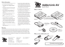
Connection overview
• For full explanations of connections, including cascade
connections, please refer to the full user guide provided
on the CD-ROM and also at www.adder.com.
• Please consult the Safety information on the rear page
of this quick start guide.
Locations
Please consider the following important points
when planning the positions of your AdderLink AV
modules:
• Take care not to exceed the maximum link
cable lengths (please refer to the section
‘Making cascade connections’ in the main user
guide for a full explanation).
• Ensure that the transmitters are as close as
possible to the source PC system and the
receivers are similarly close to the display
modules. Use video connection cables that are
correctly shielded and are no longer than 6m
in length.
• Wherever possible, choose routes for the
CATx twisted pair link cables that avoid mains
power cables.
• Remember a mains power socket is required
for each transmitter and receiver.
Resolutions and cable lengths
The maximum resolutions achievable are:
1600 x 1200 x 60Hz at 200m and 1280
x 1024 x 60Hz at 300m. If you are using
lower resolutions then it may be possible
to achieve longer transmission distances
although we do not recommend runs
longer than 300m in any installation. If
you are running shorter cables then it may
be possible to use more cascades.
Adjustments for skew compensation
between colours (AV101 and AV200
models only)
Brightness adjustment dial
Sharpness adjustment dial