1-1 (E)
HKDW-702
Section 1
Installation
1-1. HKDW-702 Configuration
The HKDW-702 consists of the following:
. DC-110A board (1)
. Shield plate (1)
. Screw P2 x 4 (2)
. Precision screw P1.4 x 3.5 (3)
. VIDEO OUT assembly (1)
. Installation Guide (1)
. Installation Manual (1)
In addition to the Installation Manual, the following manuals are available.
. HDW-750 Operation Manual (Supplied with HDW-750)
This manual is necessary for application and operaion of HDW-750.
Part number: 3-205-316-0X
. HDW-750, HKDW-702/703 Maintenance Manual Volume 1 (Available upon request)
This manual intended for use by trained system and service engineers describes (the circuit overview,
character display functions, the main part replacements, electrical alignment, etc.) required for parts-
level service.
For obtaining, contact your local Sony Sales Office/Service Center.
Part number: 9-968-591-0X
. HDW-750, HKDW-702/703 Maintenance Manual Volume 2 (Available upon request)
This manual is intended for use by trained system and service engineers, and describes the information
regarding the parts list, semiconductor pin assignments, block diagrams, schematic diagrams and board
layouts.
For obtaining, contact your local Sony Sales Office/Service Center.
Part number: 9-968-582-0X
1-2. Installation Procedure
Outline of the installing the HKDW-702 to the HDW-750 is listed as follows. For the details of the
installation work, refer to the respective sections.
Installation procedure Sections describing the detailed procedure
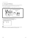
1. Confirming the AT ROM Version 1-3. Confirming the AT ROM Version
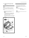
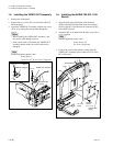
2. Opening the Inside Panel 1-4. Opening and Closing the Inside Panel
3. Installing the VIDEO OUT Assembly 1-5. Installing the VIDEO OUT Assembly
4. Installing the HKDW-702 (DC-110A Board) 1-6. Installing the HKDW-702 (DC-110A Board)
5. Closing the Inside Panel 1-4. Opening and Closing the Inside Panel
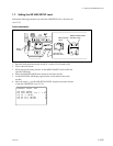
6. Setting the SD VBS SETUP level
*
1-7. Setting the SD VBS SETUP Level
7. Operation Check 4-8-2. Select the output signal.
Select an analog composite signal or SDI signal to (Refer to HDW-750 Operation Manual.)
be output from the VBS/SDI OUT connector.
Confirm that the selected signal is output from the
connector.
* : This item is required when the setup level is set to 7.5 %.


