


61280012L1-10A © ADTRAN, 2002 2
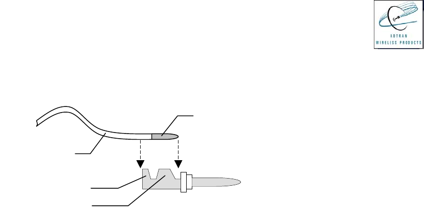
Care should be taken when crimping the crimp terminals onto the bare conductors. The
centermost flanges should make contact with the bare conductor, while the outermost flanges
should crimp onto the insulator. See Figure 2 below for details.
Figure 2 – Crimp Terminal Details (side view)
The strain relief hardware should be installed after crimping each pin to a crimp terminal and
inserting each into the appropriate receptacle position. Twist the strain relief shell onto the
receptacle prior to tightening the strain relief screws. The strain relief should apply pressure to
the outer twisted pair sheath, which bundles the individual conductor insulators, and not to the
individual insulators themselves.
Insulator
(
x4
)
Bare Conductor (x4)
Crimp Terminal (x4)
Center Flan
g
e
Outer Flan
g
e