


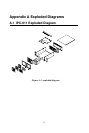


Chapter 2 System Setup
If you want to connect any USB device or PS/2 keyboard to the system, you
could use the front accessible USB & PS/2 connectors. The system LED
display is on front of door cover and shows system power status, system
voltages, and HDD activity. Power switch and system reset are behind the
door.
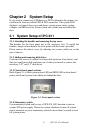
2.1 System Setup of IPC-611
2.1.1 Attaching the handles and removing the top cover
The handles for the front panel are in the accessory box. To install the
handles, simply secure them to the front panel with the screws provided.
Please remove the chassis cover by releasing two screws which are on the
rear of chassis.
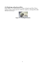
2.1.2 Adding and removing disk drives
Undo the four screws of cushion to release disk enclosure from chassis, and
then you could move disk enclosure out of chassis to install or remove the
necessary 5.25” and 3.5” disk drives.
2.1.3 Chassis front panel sections
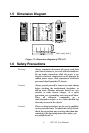
Refer Figure 2.1 to find system power LED and HDD LED on front bezel;
power switch and system reset which are behind the door.
Figure 2.1: Front panel section
2.1.4 Momentary switch
Use momentary switch and by way of ATX (PS_ON) function to turn on
system ATX power supply. Please use system shutdown to turn off system
power automatic or press momentary switch for more than 5 seconds to turn
off system power.
IPC-611 User Manual
8