


User’s Manual
Video Input
A group of BNC connectors are available for video input streams from
installed cameras. The number of connectors is equal to the number of
channels; the DRT16 / DRT8 DVR has 8/ 16 BNC connectors on the rear
panel, respectively.
Video Looping
Plenty of BNC connectors are positioned on the real panel for looping out the
video input.
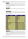
Alarm I/O & RS485
The unit provides an alarm I/O and RS485 port that offers user the flexibility
required to connect the unit to the other device. The definitions of pins are
listed in the below table:
Pin Definition Pin Definition
1
RS485 D+
17
Alarm In 1
2
RS485 D-
18
Alarm In 2
3
Ground
19
Alarm In 3
4
Normal Close 1
20
Alarm In 4
5
Common Node 1
21
Alarm In 5
6
Normal Open 1
22
Alarm In 6
7
Ground
23
Alarm In 7
8
Normal Close 2
24
Alarm In 8
9
Common Node 2
25
Alarm In 9 (for 16ch Model)
10
Normal Open 2
26
Alarm In 10 (for 16ch Model)
11
Ground
27
Alarm In 11 (for 16ch Model)
12
N/A
28
Alarm In 12 (for 16ch Model)
13
N/A
29
Alarm In 13 (for 16ch Model)
14
N/A
30
Alarm In 14 (for 16ch Model)
15
Ground
31
Alarm In 15 (for 16ch Model)
16
Ground
32
Alarm In 16 (for 16ch Model)
Audio In / Out
The DRT16 / DRT8 DVR provides two channels of audio recording and
playback. Audio In RCA connector is offered for connecting an audio source
device (e.g. external amplified microphone) to the unit; Audio Out RCA
connector is offered for connecting an audio output device (e.g. amplified
speakers) to the unit.
10