


For full warranty information, refer to the AMX Instruction Manual(s) associated with your Product(s).
9/07
©2007 AMX. All rights reserved. AMX and the AMX logo are registered trademarks of AMX.
AMX reserves the right to alter specifications without notice at any time.
3000 RESEARCH DRIVE, RICHARDSON, TX 75082 • 800.222.0193 • fax 469.624.7153 • technical support 800.932.6993 • www.amx.com
93-0148-04 REV: E
2. Remove the battery door (See Inserting the Lithium-Ion Battery Into the
Mio R-4).
3. Connect the mini USB programming cable (FG10-5965) into the
programming jack.
4. Connect the other end of the USB cable to the USB port on your
computer.
5. Configure the communication parameters in TPDesign4.
Device Setup Pages - Setup Menu
The Setup Menu allows you to set and check the following device features:
• Project Information Functions
• Remote & Display Settings
• Date/Time Settings
• Sound Settings
• Protected Settings
• Battery Settings
To enter the Setup Menu, press and hold the Input and Back buttons for 6
seconds. Navigate the setup pages using the on screen menu selections and
up and down arrows. For more information on the Setup Menu, please refer to
the Mio Modero R-4 User Manual, available at www.amx.com.
Protected Settings
The Protected Settings Menu allows you to set and check the following device
features:
• Options & Recovery
• Change Passwords
•Calibrate
• System Settings
• Reboot Panel
The Protected Settings Menu may be accessed through the Setup Menu.
Accessing Protected Settings menu items requires a password confirmation.
For more information on the Protected Settings Menu, please refer to the Mio
Modero R-4 User Manual, available at www.amx.com.
Note: To access the Protected Settings Menu for the first time, you must
provide the default password: 1988.
Changing Passwords
1. Select Protected Settings in the Setup Menu.
2. Select Change Passwords on the Protected Settings Menu.
3. Select one of the five passwords to be changed.
4. Enter, edit, and confirm changes to the password.
5. Select the Back button until you are out of the Setup Menu.
Calibrating the Mio R-4
1. Select Protected Settings in the Setup Menu.
2. Select the Calibrate button.
3. Touch each target as it appears on the screen.
4. If successfully calibrated, the Mio R-4 will return you to the Protected
Settings Menu.
Rebooting the Mio R-4
1. Select Protected Settings in the Setup Menu.
2. Select the Reboot Panel button.
3. Select Reboot.
System Settings
The System Settings page of the Protected Settings provides connection
status, gateway selection, and RF link information. Use the device’s up and
down arrows to move from viewable page to page.
Checking Connection Status
1. Select Protected Settings in the Setup Menu.
2. Select System Settings in the Protected Settings Menu. If the round
button at the top right of the first page is green, the system is connected.
3. Select the Back button until you are out of the Setup Menu.
Changing the Master Connection Type
1. Select Protected Settings in the Setup Menu.
2. Select System Settings in the Protected Settings Menu.
3. Select the device’s down arrow to navigate to the second page. The Type
button lists the current Master Connection type for the unit: USB or Mesh.
4. Press the Type button to select the preferred Master Connection type.
5. Select the Back button once to return to the Protected Settings menu.
6. Reboot the device from the Reboot Panel Page.
Joining a Wireless Network
1. Select Protected Settings in the Setup Menu.
2. Select System Settings in the Protected Settings Menu.
3. Press the Site Survey button. The available networks are listed below.
Use the up and down arrows to navigate the menu.
4. Select the network by pushing it on the touch screen. A pop-up page
reading "Do you wish to connect to PAN [PAN number]" will appear.
• To connect to the PAN, press the Yes button.
• To return to the Site Survey page without connecting to the PAN, press
the No button.
• If you do not make a selection within three seconds, the pop-up page will
automatically close in three seconds.
5. Select the Back button until you are out of the Setup Menu.
Battery Low Indicator
When the battery charge level is too low to sustain continuous operation, a
popup window will appear on the touchscreen reading “Battery Low” and then
“Battery Very Low”. If the device is still not returned to the charging cradle, it will
then shut down.
Battery Settings
1. Select Battery Settings in the Setup Menu.
2. The battery level will be displayed on the Battery Settings Page. The
higher the number of green lights, the higher the charge.
3. Select the Back button until you are out of the Setup Menu.
Mio Remote Charging Base
The Mio remotes are complemented with the Mio-RCC charging base. To
charge the remote from the charging base:
1. Connect the terminal end of the power supply to the bottom external
power port on the Mio remote charging base.
2. Route the cable through the provided channel so that it comes out the
side of the base.
3. Connect the power cord to an external power source.
4. Place the bottom of the Mio R-4 into the charging base so the contacts on
the device are on top of the charging contacts inside the charging base.
The Power LED on the Mio R-4 blinks red to indicate it is charging and
illuminates solid red when it is done. A full charge cycle for a depleted
battery is approximately 3 hours.
Note: Due to the wireless nature of the ZigBee network, temporary interference
may prevent a command from reaching the NetLinx master. If this happens
while increasing volume, the master may receive the command to increase the
volume but not the command to stop increasing it. Therefore, programmers
should consider setting safeguards for volume control, either established
volume limits or timeouts with the NetLinx master or more interactive
adjustment from the Mio R-4 (i.e., direct volume control), to prevent issues with
lost commands.
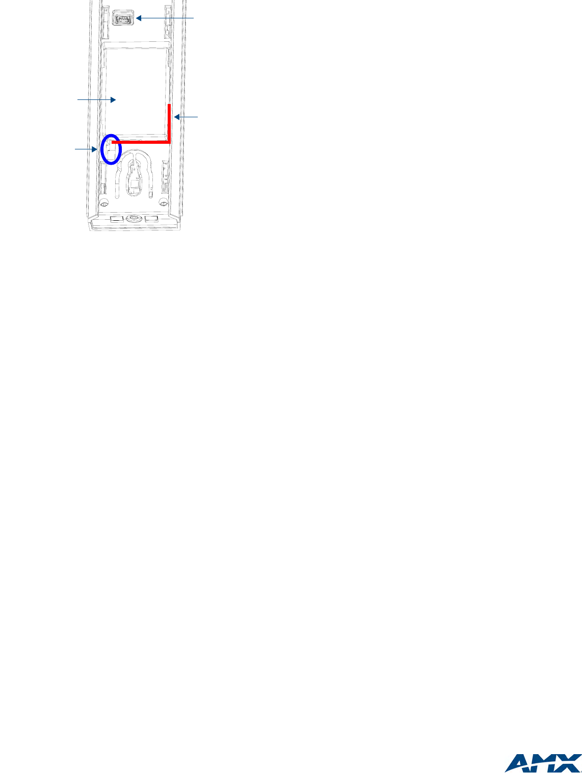
FIG. 2 Rechargeable Battery Port on The Mio Remote
Lithium-Ion Battery
Rechargeable
Battery Port
Connection
Rear view -
battery compartment
Programming Port
(USB)
Correct path for
battery wires and
connector