


For full warranty information, refer to the AMX Instruction Manual(s) associated with your Product(s).
4/07
©2007 AMX. All rights reserved. AMX and the AMX logo are registered trademarks of AMX.
AMX reserves the right to alter specifications without notice at any time.
3000 RESEARCH DRIVE, RICHARDSON, TX 75082 • 800.222.0193 • fax 469.624.7153 • technical support 800.932.6993 • www.amx.com
93-0147 REV: C
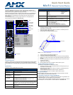
Using Connector Ports on The Mio R-1
The programming jack is used for communication between the device and
KeypadBuilder. The programming jack uses a three-wire, 2.5 mm stereo jack, you
can order the programming cable (FG10-817) from AMX if you do not currently
possess one. While loading your configuration file make sure the device is situated
as such that the batteries will not fall out. The load will fail if your batteries fall out
during the process. The Mio communicates at 115200 baud rate.
To download KeypadBuilder Configuration Files:
1. Set the Mio R-1 Download mode to ON. See the Configuration Mode section
for details.
2. Flip and turn the Mio R-1 device so that the buttons are facing away from you
and the device is upside down.
3. Holding the device in both hands, place your thumbs on the battery door and
slide the battery door free.
4. Connect the 2.5 mm stereo plug (male) end of the programming cable (FG10-
817) into the programming jack on the bottom side of the remote device.
5. If necessary, connect the DB-9 end of the programming cable to the female
DB-9 connector on the DB-9 extension cable (FG10-727).
6. Connect the female DB-9 terminal end of the extension cable to the port on the
back of your computer.
7. Configure the communication parameters in KeypadBuilder.
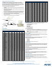
IR Code Matrix
The IR Code emitted depends upon which of the 6 configurable modes is selected.
Below is the list of codes for each button within each mode.
Configuration Mode
The configuration mode allows you to set the following device features:
• IR Transmit Mode (38 KHz or 455 KHz)
• Timeout Adjustment
• Download Mode
• Debug Mode
• Battery Type
• LED Awake Brightness
• LED Sleep Brightness
To enter configuration Mode:
1. Press and hold the STOP button and the INPUT button. The two buttons must
be pressed within 0.1 seconds of each other and held down for 2 seconds. The
device indicates you are now in configuration mode. See below for available
modes.
2. Press the EXIT key when you are finished.
Note: Your settings will not be lost in the event your batteries die or are removed.
IR Transmit Mode
Pressing button "1" on the remote toggles the IR transmission mode between 38KHz
and 455KHz. The display indicates the current mode.
Timeout Adjustment
Press button "2" on the remote to change the sleep timeout from the default. Each
time "2" is pressed, the sleep timeout raises incrementally. The
pre-determined sleep timeouts are:
• 3 seconds
• 6 seconds
• 9 seconds
• 12 seconds
The display indicates the selected sleep timeout.
Download Mode
Pressing "3" on the remote toggles the Download mode OFF and ON. The Download
mode must be ON before you can download a file to the Mio R-1 device. While the
Download mode is ON the device will not go to sleep. A power cycle will return the
device to Download OFF.
Debug Mode
Pressing button "4" on the remote toggles development mode between ON and OFF.
The display indicates the selected mode. In development mode, the display shows
the IR code assigned to buttons when pressed.
This mode is useful to the programmer when determining what IR codes are
associated to each mode.
Battery Type
Pressing button "6" on the remote toggles the battery type between Normal and
Recharge. The display indicates the selected type. The type of battery in the Mio R-1
dictates the battery type you need to set.
LED Awake Brightness
Pressing button "7" on the remote toggles the Power LED brightness mode from
LOW to MED and then HIGH. The display indicates the selected mode.
LED Sleep Mode Brightness
Pressing button "8" on the remote toggles the Sleep brightness mode from OFF to
LOW and then MED. The Sleep brightness is the state the Mio R-1 assumes while in
the charging cradle.
FIG. 3
Connecting The Keypad Device to Your PC
IR Code Matrix
Button Label Mode 1 Mode 2 Mode 3 Mode 4 Mode 5 Mode 6
1 Power Symbol 9 49 89 129 169 209
2 GUIDE 38 78 118 158 198 238
3 EXIT 37 77 117 157 197 237
4 MENU 31 71 111 151 191 231
5 INFO 39 79 119 159 199 239
6 L 32 72 112 152 192 232
7 M 33 73 113 153 193 233
8 K 34 74 114 154 194 234
9 A 35 75 115 155 195 235
10 SELECT 36 76 116 156 196 236
11 VOL + 24 64 104 144 184 224
12 VOL - 25 65 105 145 185 225
13 CH + 22 62 102 142 182 222
14 CH - 23 63 103 143 183 223
15 LAST 40 80 120 160 200 240
16 MUTE 26 66 106 146 186 226
17 1 11 51 91 131 171 211
18 2 12 52 92 132 172 212
19 3 13 53 93 133 173 213
20 4 14 54 94 134 174 214
21 5 15 55 95 135 175 215
22 6 16 56 96 136 176 216
23 7 17 57 97 137 177 217
24 8 18 58 98 138 178 218
25 9 19 59 99 139 179 219
26 INPUT 29 69 109 149 189 229
27 0 10 50 90 130 170 210
Stereo plug male
DB-9 connector
Cable FG10-817 to cable FG10-727
to PC
programming
cable
Keypad device
Programming
jack
Mio R-1
IR Code Matrix (Cont.)
Button Label Mode 1 Mode 2 Mode 3 Mode 4 Mode 5 Mode 6
28 ENTER 21 61 101 141 181 221
29 A (Macro 1) 250 250 250 250 250 250
30 B (Macro 2) 251 251 251 251 251 251
31 C (Macro 3) 252 252 252 252 252 252
32 TV (Mode 1) 241 241 241 241 241 241
33 SAT (Mode 2) 242 242 242 242 242 242
34 DVD (Mode 3) 243 243 243 243 243 243
35 CD (Mode 4) 244 244 244 244 244 244
36 AUX (Mode 5) 245 245 245 245 245 245
37 LGHT (Mode 6) 246 246 246 246 246 246
38 STOP B 2 42 82 122 162 202
39 REC J 8 48 88 128 168 208
40 PAUSE C 3 43 83 123 163 203
41 S. REV Z 7 47 87 127 167 207
42 PLAY A 1 41 81 121 161 201
43 S. FWD Y 6 46 86 126 166 206
44 REW E 5 45 85 125 165 205
45 FWD D 4 44 84 124 164 204