


Specifications subject to change without notice
© 2006 Atlas Sound Printed in U.S.A. 000706 ATS001458 RevC 7/06 SL10-2026
1601 JACK MCKAY BLVD. / ENNIS, TEXAS 75119 U.S.A.
TELEPHONE: (800) 876-3333 / FAX (800) 765-3435
AtlasSound.com
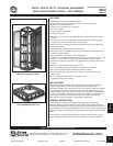
The Atlas Sound FMA series features completely redesigned "hat" sections for added
strength & greater versatility in rack rail positioning. The hat sections include a rack
rail slot along with holes spaced the entire length of the hat section to allow for easy,
secure positioning of the rack rails. This newly designed hat section is also spaced
in the cabinet to allow the installation of standard 19" blank panels vertically inside
the cabinet. This is perfect for "stick-on" type accessories like Atlas Sound DC power
supplies & relays. Hat sections also feature slotted cut-outs for clean, organized wire
management.
For optimum wire management, unique, removable 2RU high panels are positioned
behind cutouts at the top & bottom on the rear of the cabinet. These panels include
a variety of knockouts ranging in size from
3
⁄8" to 1
1
⁄4" to facilitate rigid or flexible
conduit.
3
⁄8" knockouts (x2) are also included on this panel to allow installation of
BNC connectors commonly used for diversity wireless microphone systems. The
cabinet top sections offer large, vent openings for maximum ventilation. This comes
in especially handy when thermal sensitive amplifiers and/or digital rack mount
equipment are mounted in a FMA cabinet.
Leg levelers are included with the FMA series at no additional cost to provide
alignment regardless of floor evenness but in instances where maneuverability of the
cabinet is required, an optional caster kit allows easy positioning without significantly
increasing the cabinet’s overall height.
Cabinets include two pair (front/back) 11 gauge plated steel rack rails tapped 10-
32 and include the new Atlas Sound RU indicators to aid in aligning equipment
during installation. Threaded inserts are included on the front of the cabinet to save
installation time when a front door is required.
Optional FMA series side panels "swing–out" for easy serviceability of equipment
housed in the cabinet while maintaining security. These heavily reinforced side panels
install easily on unique "lift-off" hinge assemblies. All mounting holes and cabinet
hardware is provided to join multiple FMA & G series cabinets.
UL listing & seismic rating pending.
OPTIONAL ACCESSORIES
Vented side panels
Matches FMA44-36LRPV – FMA44-36G
Matches FMA44-25LRPV – FMA44-25G
Matches FMA35-25LRPV – FMA35-25G
FMARTK25
Includes
(2)
locking swivel and (2) rigid casters with mounting hardware.
For FMA44-25G and FMA35-25G models only
Perforated top panels
TPP-19-25-962 – Matches FMA44-25G, FMA35-25G
Solid top panels
TPS-19-25-962 – Matches FMA44-25G, FMA35-25G
TPS-19-36-962 – Matches FMA44-36G
High power top mounting fan kits
EFT19-25-962 – Matches FMA44-25G, FMA35-25G
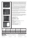
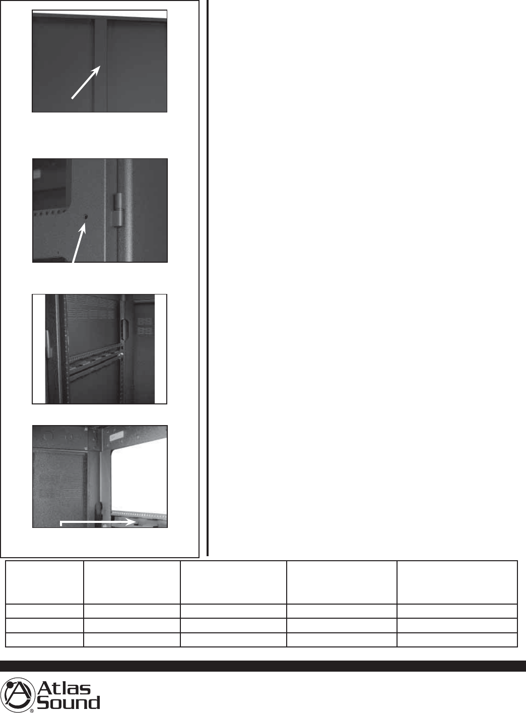
Pre-drilled holes allow multiple
cabinets to be connected or
ganged
Reinforced stiffeners on all side
panels. Lift-off locking side panels–
"swing-out" design facilitates easy
service access
Increased vent space on top
sections
Hat section features integrated
provision for clean wire
management
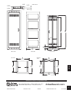
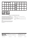
MODEL
Rack Rail to 1.0" Front
Door Clearance (with
front rack rail in foward
most position)*
Rack Rail to 3.0" Front
Door Clearance (with front
rack rail in forward-most
postition)*
Overall Usable Mounting
Depth (front rail face to rear
rail face with rails at full front
extension front to back)
Front Rack Rail to Rear Door
Clearance (with front rack rail
in farthest forward position)
FMA44-36G 2.0" (50.8mm) 3.813" (96.8mm) 34.08" (865.6mm) 34.98" (888.5mm)
FMA44-25G 2.0" (50.8mm) 3.813" (96.8mm) 23.58" (598.9mm) 24.48" (621.8mm)
FMA35-25G 2.0" (50.8mm) 3.813" (96.8mm) 23.58" (598.9mm) 24.48" (621.8mm)
* Does not account for 3.5" area in center of cabinet where door handle and lock could cause interference with equipment knobs if rack rails are located fully forward.