


4
www.atlona.com
Toll free: 1-877-536-3976
Local: 1-408-962-0515
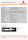
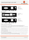
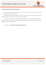
1.2. Rear Panel
CONNECTION AND OPERATION
1 2 3 54
1. RS-232 Port
2. LINK
3. RJ-45 Output
4. Power on Light
5. Power input, 5V DC
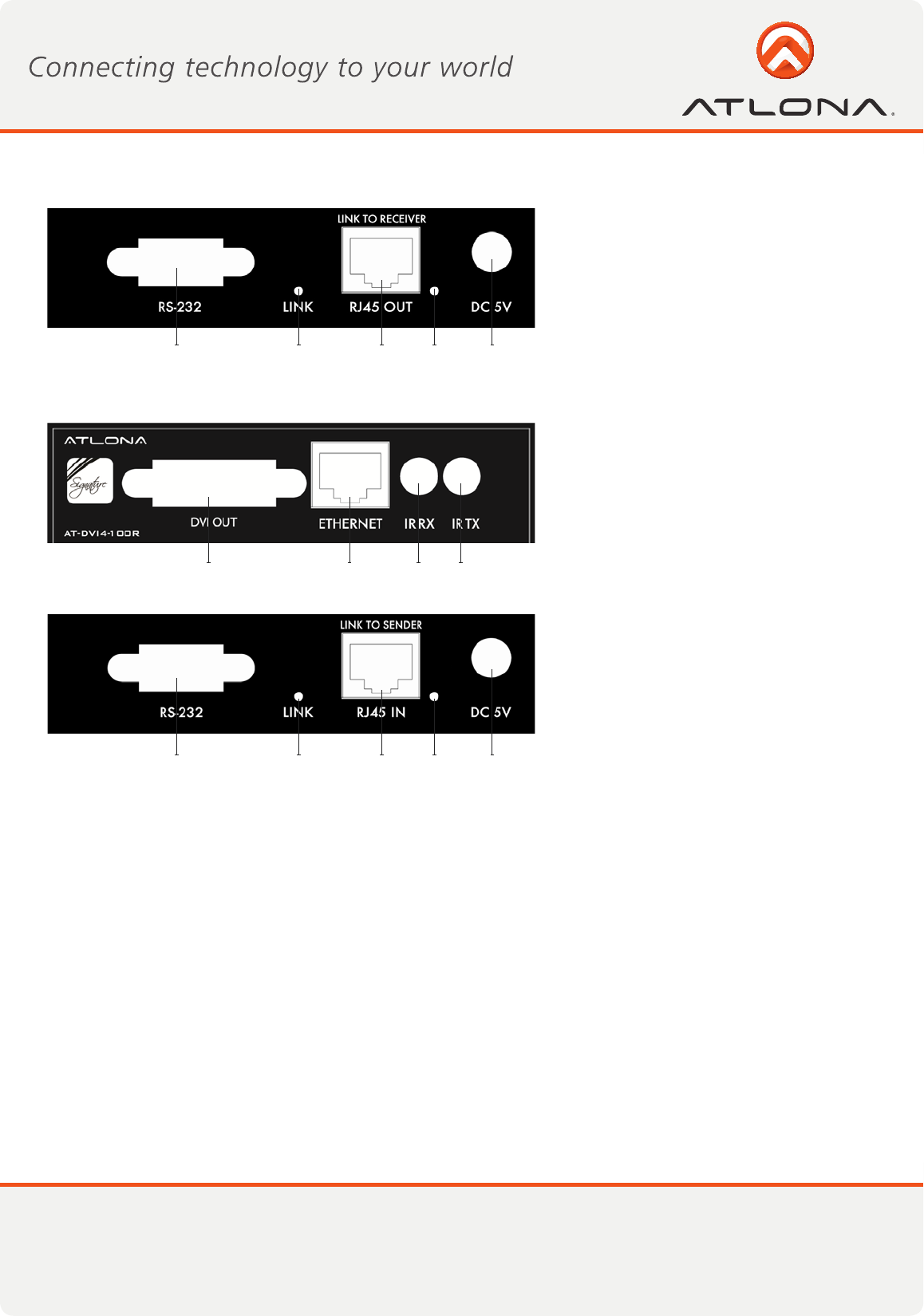
1. DVI Output
2. Ethernet Connector
3. IR RX
4. IR TX
2. Receiving Module
2.1. Front Panel
1 2 3 4
2.2. Rear Panel
1 2 3 54
1. RS-232 Port
2. LINK
3. RJ-45 Input
4. Power on Light
5. Power input, 5V DC
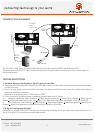
1. Connect the DVI Source e.g., Computer, Video Codec, switch to the AT-DVI4-100SR (transmitting unit)
2. Connect the DVI Display e.g., Projector, LCD/LED or a switch to the AT-DVI4-100R (receiving unit)
3. Terminate the CAT5, 6 or 7 wire with 568B termination and use a tester to make sure all pins are wired correctly
before connect it to the DVI-100SR modules.
4. Connect the power supplies to both transmitter and receiver and the video and in a few seconds the video should
appear on the display.
5. For users who want to transmit IR signal from the Display to the source, should connect the IR RX to the receiver unit
and IR TX to the transmitter.
6. For users who want to transmit IR signal from the Source to the Display, should connect IR RX to the transmitter and
IR TX to the receiver module.
Note: It is very important to connect IR RX and IR TX to its proper connections. If the IR TX is connected to the IR RX connection or
other way around, the IR sensors will get damaged.
7. For users who want to transmit RS232 signal from the control system or computer to the display device, should con-
nect the RS232 (DB9) cables to the transmitter and receiver modules respectively.
8. RS232 Port on the transmitter and Receiver can also be used for firmware upgrades to the DVI4-100SR modules.