


Connection and Installation
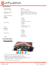
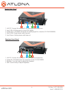
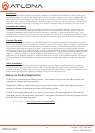
Receiver Back Panel
1. RS-232: Use a 9pin to 9pin cable to connect to a RS-232 device
2. Audio Out: Connect to an analog audio device (Ex. AT-PA100-G2)
3. S/PDIF Out: Connect to a digital audio device (Ex. AVR)
4. VGA Out: Connect to a VGA display
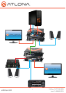
1. Connect VGA source, audio source, and RS-232 devices to the AT-VGA-RS300S (Sender)
2. Connect VGA display, audio, and RS-232 devices to the AT-VGA-RS300R (Receiver)
3. Connect a CAT5/5e/6 cable between the transmitting and receiving units.
4. Plug in 5V DC power supply unit to the power jack of the AT-VGA-RS300R (Receiver)
5. Plug in 5V DC power supply unit to the power jack of the AT-VGA-RS300S (Sender)
6. Adjust brightness with the gain rotary.
7. Use the equalizer dial to adjust sharpness.
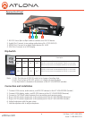
Note: 1. TxD: The 3rd pin of RS-232, which is in charge of sending data
2. RxD: The 2nd pin of RS-232, which is in charge of receiving data
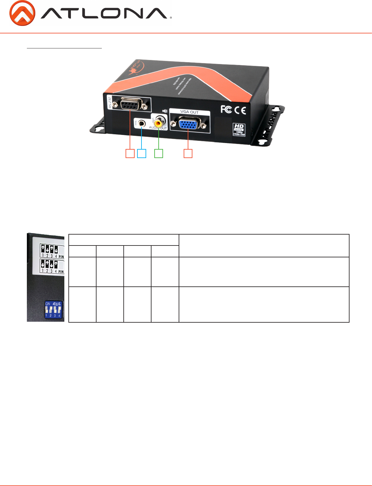
3. The Dip Switch is located on the bottom of the AT-VGA-RS300S (sender)
Dip Switch
Dip Switch Position
Description
Pin 1 Pin 2 Pin 3 Pin 4
On h Off i On h Off i
Sender & Receiver Extender Mode -
TxD of
AT-VGA-RS300S
is connected to TxD of
AT-VGA-RS300R
RxD of
AT-VGA-RS300S
is connected to RxD of
AT-VGA-RS300R
Off i On h Off i On h
Master to Slave Mode -
TxD of
AT-VGA-RS300S
is connected to RxD of
AT-VGA-RS300R
RxD of
AT-VGA-RS300S
is connected to TxD of
AT-VGA-RS300R
1 2 3 4
atlona.com
Toll free: 1-877-536-3976
Local: 1-408-962-0515
6