


4
AVR1909
8297A-AVR-04/10
3.4 The SPI interface
The Display Xplained module uses a simple SPI interface to communicate with the
LCD module. This consist of a Chip-Select (CS) line, a clock line (SCL), and two data
lines (SDI/SDO). The SPI is operated in mode 3, i.e. inactive clock is ‘high’, and data
is latched on rising clock edge.
3.5 The SPI/USART MUX resistors
The ATxmega128A1 has swapped the MOSI and SCK signals between using the
regular SPI and using the USART in master SPI mode, which is available on the
same pins. In order to offer the possibility to use both interfaces, a simple 0-ohm
resistor mux is added to the Display Xplained module. It is currently set up to use the
USART in master SPI mode. To switch to the regular SPI mode, move the two
resistors mounted in position R111/R114 to position R112/R113.
See schematic diagram and PCB assembly drawing for details on where to find these
resistors. Note that they are placed under the LCD flexprint cable, so this needs to be
disconnected from the FPC connector to get access to the resistors Please refer to
Figure 2-1 page 2.
3.6 The LCD Tear-Enable signal (TE)
The LCD Module has an output signal that indicates when the display can be updated
without getting any tearing effects. This signal basically indicates the scan retrace
period of the display, meaning the time-period after the last pixel update and before
the first pixel is written again. This period can be used to update the graphical RAM,
and the update will be shown in the next scan period. For further details, see the
Himax HX8347-A datasheet and application notes.
3.7 The LCD Reset signal
This signal is an input to the LCD module and is used to reset it. It has a pull-up
resistor connected to avoid unintended resets. For further details, see the Himax
HX8347-A datasheet and application notes.
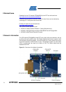
4 Connectors
The Display Xplained module has five 10-pin 100mil headers. Two are used for
programming/debugging interface to the Xplain kit. One is used for SPI interface and
the backlight control of the LCD module. One is used for the touch interface to the
LCD module. The last one is only used as a mechanical stabilizer to the Xplain kit.
Note that the female SMD mounted pin-headers might get damaged if not handled
carefully. The plastic insulation might come off and exposes the conductors.
The last connector on the Display Xplained module is the FPC connector for the LCD
module.
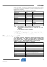
4.1 Programming headers (J103/J104)
The AVR XMEGA™ can be programmed and debugged by connecting an external
programming/debugging tool to the “JTAG & PDI XMEGA” pin header (J100). The pin
header is having a standard JTAG programmer pinout (refer to online help in AVR
Studio
®
), and tools like the JTAGICE mkII or the AVR ONE! can thus be connected