


6
To change channel automatically
Press and hold the Set/Scan button for about two seconds. The current
channel will flash three times quickly; then the system will begin to
scan for the next open channel. When it finds an open channel, it will
flash the open channel three times and then set the channel. (If an
open channel is not found, the automatic scan will return to the original
channel and flash 5 times.)
Transmitter On…
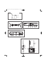
Before turning on the transmitter, use the provided screwdriver to set
the transmitter channel selector switches (Fig. D on page 2 and Fig. H
on page 3) to the same number that is displayed on the receiver. Select
channels 1-8 (channels 9 and 0 are for service use). The transmitter
may be either on or off when changing channels (frequencies). When
changing channels with the transmitter on and unmuted, the LED will
turn red as the adjustment is being made; it will turn green when the
channel is set.
(When changing channels with the transmitter on and muted, the LED
will remain red during and after channel adjustment, as long as the
transmitter is muted; when the transmitter is unmuted, the LED will
turn green.)
The transmitters have a soft-touch Power Switch. When the
transmitter is “on,” the transmitter produces both RF and audio.
When the transmitter is switched on and in normal operation, the
receiver’s diversity indicators will display which antenna is active.
Setting Levels
Correct adjustment of transmitter audio input, receiver audio output,
and mixer/amplifier input and output levels is important for optimum
system performance.
ATW-T702 Handheld Transmitter
The 700 Series handheld transmitter trim (volume) control (Fig. H on
page 3) has factory pre-set audio input levels. Factory setting is full
clockwise, maximum gain.
Set the receiver’s AF Level control to its full clockwise position
(maximum). (Fig. C on page 2).
While speaking/singing into the microphone at typically loud levels,
check the AF peak indicator on the receiver. If the AF peak indicator is
easily illuminated and distortion is heard through the system, it may be
necessary to adjust the transmitter audio input level.
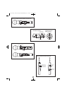
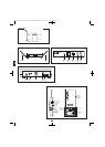
To adjust the transmitter audio input level, unscrew the lower body
cover and slide it downwards, exposing the screwdriver and trim
control (Fig. H on page 3). Remove the screwdriver and gently
turn the
trim control counterclockwise until the AF peak indicator is illuminated
only on audio peaks.
Return the screwdriver to its clip and close and secure the lower body.
No further transmitter gain adjustments should be needed, as long as
the acoustic input does not change significantly.
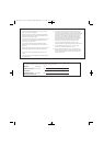
Handheld Transmitter Interior View (Fig. H)
ATW-T701 UniPak
™
Transmitter
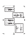
Trim controls in the UniPak transmitter (Fig. I) will enable you to use
microphones or instruments with different output levels.
1 For MIC: Set MIC (microphone trim) control fully clockwise
(maximum) and INST (instrument trim) control fully counter
clockwise (low).
For INSTRUMENT: Set INST (instrument trim) control fully
clockwise (maximum) and MIC (microphone trim) control fully
counterclockwise (low).
2. Set the receiver’s AF Level control to its full clockwise position
(maximum). (Fig. C on page 2).
3. Plug the mic or instrument into the transmitter and power up the
system.
4. For MIC: Make an initial adjustment of the mixer’s level controls
that will allow audio through the system.
For INSTRUMENT: Make an initial adjustment of the instrument
amplifier input level control that will allow audio through the
system.
5. For MIC: While speaking/singing into the microphone at typically
loud levels, check the AF peak indicator on the receiver. If AF peak
indicator is easily illuminated and distortion is heard through the
system, it may be necessary to adjust the transmitter audio input
level. To adjust the transmitter audio input level, gently
turn the
microphone trim control counterclockwise until the AF peak
indicator is illuminated only on audio peaks.
For INSTRUMENT: While playing the instrument at typically loud
levels, check the AF peak indicator on the receiver. If AF peak
indicator is easily illuminated and distortion is heard through the
system, it may be necessary to adjust the transmitter audio input
level. To adjust the transmitter audio input level, gently
turn the
instrument trim control counterclockwise until the AF peak indicator
is illuminated only on audio peaks.
6. For MIC: While again speaking/singing into the microphone at
typically loud levels, adjust the mixer’s input trim control so the
highest sound pressure level going into the microphone causes no
input overload in the mixer, and yet permits the mixer’s channel and
output level controls to operate in their “normal” range (not set too
high or too low).
For INSTRUMENT: While again playing the instrument at typically
loud levels, adjust the receiver’s AF Level control so the highest
signal level causes no input overload in the instrument amplifier and
yet permits the amplifier’s input level controls to operate in their
“normal” range (not set too high or too low).
Note: If the mixer cannot be adjusted to operate in its normal range
without distortion, adjust the receiver’s AF Level Control (turn
counterclockwise) until the mixer/amplifier is no longer overloaded.
Note: RF power may be set to high or low via the RF power select
switch on the side of the UniPak transmitter. (Fig. I.) While the high
setting normally provides maximum operating range, the low setting
will help extend battery life. The low setting may also be preferred in
multi-channel systems, or when operating very close to the receiver,
to reduce the possibility of interference or overload.
UniPak Transmitter Side View (Fig. I)
RF Interference
Please note that wireless frequencies are shared with other radio
services. According to the National regulations, “Wireless
microphone operations are unprotected from interference from other
licensed operations in the band. If any interference is received by any
Government or non Government operation, the wireless microphone
must cease operation...” If you need assistance with operation or
frequency selection, please contact your dealer or Audio-Technica.
Extensive wireless information also is available on the Audio-Technica
Web site at www.audio-technica.com.
System Operation (continued)
See illustration figures page 3
E
N
CAUTION! The small trimmer controls are delicate; use only the
supplied screwdriver. Do not force the trimmers beyond their
normal 180° range of rotation.
Return the screwdriver to its storage clip when not in use
OM 700 Series (March 2009).qxd:12MAY3000OM.qxd 12/03/09 9:58 Page 6