


Cable
Clamp
Antenna Mounting
The attractive molded housings are easily removable for
installation or adjustment. Simply remove the two silver-color
screws located at the rear of each housing and gently pull
the housing forward, away from the black metal rear plate
(Fig. B).
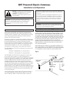
For portable or temporary use, install the included AT8667
brackets with BNC connectors and
5
/
8
"-27 threaded mounts.
Attach each bracket to an antenna using two small, black
machine screws (included). Direct the screws from
inside
the
antenna’s rear plate through the inner pair of small holes, and
screw them into the tapped holes in the bracket. Prepare the
free ends of the short cables as shown in Figure C.
For permanent installation, the antennas may be attached to a
wall or other vertical support with appropriate fasteners. They
also may be mounted to a single-gang electrical box, via the
outer pair of small holes on the rear plate (using #6-32 screws,
not included). When installing, position the units so the gain
switches and screw terminals face to the
right.
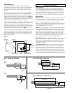
The PC board may be removed for safety or convenience while
installing the metal rear plate, if desired. Simply remove the
two screws indicated in Figure B. When re-mounting the PC
board, note that the board goes on the “outside” of the rear
plate’s mounting ears.
Internal Connections
Cable Selection
Screw-terminal connections in the antennas are designed for
use with RG58-type or RG8-type RF transmission cables, or
with Asian RF cable types 3D or 5D. Make certain the cable
selected is intended for UHF operation and has a full braided
copper shield, not just a metalized foil shield. For runs of 25'
(8 m) or more, a low-loss cable such as RG8 should be used.
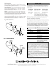
Cable Stripping
RG58:
Observing the dimensions in Figure C, remove a section
of the outer jacket and a portion of the inner coax insulation,
being careful not to cut or nick the shield or center wires (C1).
Note: If the cable jacket’s outer diameter is less than
7
/
32
"
(0.21", 5.3 mm), wrap the jacket with electrical tape to build up
its diameter before folding back the braid over the jacket (C2).
Trim the shield wires to
9
/
16
" (15 mm).
RG8:
When using RG8-type cable, more jacket material needs
to be removed and partially replaced with shrink tubing. When
installing the tubing, heat the tubing and cable only enough to
shrink the tubing. Allow the cable to cool fully before manipu-
lating it further. The drawings in Figures D and E are actual-
size; the shrink-tubing indications show the actual length of
pieces to be cut, and their correct placement on the cable. Cut
the required pieces from the included shrink tubing.
RG8 / Rear exit:
When connecting antennas from the rear, fol-
low the cable-stripping dimensions in Figure D. Then install a 1"-
long (25 mm) piece of shrink tubing as indicated. Remove the
cable clamp and carefully insert the cable end into position
through the rear plate.
RG8 / Bottom exit:
When connecting antennas through the
opening in the antenna housing, follow the cable-stripping
dimensions in Figure E. Then install a 2.5"-long (63 mm) piece
of shrink tubing as indicated. Remove the cable clamp and
carefully position the cable to exit at the bottom edge of the
rear plate. The end of the cable’s jacket must be located about
1
/
4
" (6 mm) beyond the end of the rear plate to clear the bottom
of the housing. Then secure the clamp and center conductor.
Lo
Mid
Hi
Fig. B
Fig. C RG58, 3D, 5D Cables
Antenna
Housing
Power
Indicator
Rear Plate
PC
Board
Mounting
Screws
Cable Clamp
Screw Locations
Gain
Switch
Housing Screw
Center
Conductor
0.79"
(20 mm)
0.59"
(15 mm)
0.59"
(15 mm)
0.2"
(5 mm)
Fig. D RG8 Cable - Rear Exit
0.59"
(15 mm)
1.22" (31 mm)
2.00" (51 mm)
0.2"
(5 mm)
Shrink Tubing
1" (25 mm)
Fig. E RG8 Cable - Bottom Exit
Shrink Tubing
2.5" (63 mm)
0.59"
(15 mm)
0.2"
(5 mm)
2.68" (68 mm)
3.46" (88 mm)
(C1)
(C2)