


11
CHAPTER 5: Operation
5. Operation
5.1 RS-232 Circuitry
The RS-232 side of the RS-232↔RS-422/485 Converter (Data Only) is composed of
the RS-232 drivers and receivers, the delay circuitry, and other circuitry necessary
to operate the RS-232 control lines.
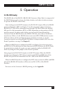
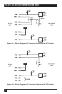
Data traveling from the RS-232 interface to the RS-422/485 interface: When the RS-232
port is configured as DCE (see Figure 5-1 on the next page), data received on
RS-232 Pin 2 (TD) will be transmitted out through TXA and TXB on the RS-422/
485 port. For this transmission, RTS (or DTR, depending on the position of W18)
must be asserted. In other words, before you can send any data through the
Converter from the RS-232 side to the RS-422/485 side, one of these conditions
must be met: Either (1) the RS-232 device must assert RTS/DTR and then receive
CTS true (that is, ask for and then be given permission to send), or (2) the
Converter must be set to keep RS-422/485 driver is always enabled (W15 set to the
B and C position—see step 3 in Chapter 3).
When the RS-232 port is configured as DTE (see Figure 5-2 on the next page),
RS-232 Pin 8 (CD) performs the same function as RTS/DTR does for DCE (it asks
for permission to send). Or, again, you can constantly enable the RS-422/485
driver by setting the W15 jumper to the B and C position.
Data going from the RS-422/485 interface to the RS-232 interface: When the RS-232
interface is configured as DCE, data received on the RXA and RXB pins of the
RS-422/485 port will be transmitted out Pin 3 (RD) of the RS-232 interface.
When the RS-232 interface is configured as DTE, data received on RXA and RXB
pins of the RS-422/485 interface will be sent out Pin 2 (TD) of the RS-232
interface.
For more on the Converter’s RS-232 pinning, see the Appendix.