


Video Recorder 630/650 Series Hardware setup | en 27
Bosch Security Systems Installation and Operation manual F.01U.169.663 | v2.0 | 2012.02
4.8 External alarm I/O connection
Alarm inputs and outputs are supplied screw down terminal blocks. The screw terminal blocks
are supplied with the unit.
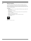
Connecting the inputs
Each (alarm) input line can be switched by a contact from an external device between an
numbered input and ground (G). Wire them as either Normally Open (N/O) or Normally
Closed (N/C). Configure the alarm inputs as N/O or N/C in the menu system. The default is N/
O.
Specifications
Alarm input impedence: Internal pull-up 10 kOhm to +5 V
Input voltage range: -2 VDC minimum to 15 VDC maximum
Input voltage threshold: low voltage 0.5 V maximum, high voltage 2 V minimum
Cable cross section: AWG 26-16 (0.13-1.5 mm2)
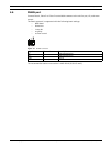
Connecting the alarm outputs
The four alarm output relays respond to input alarms and triggers. Configure the alarm
outputs as N/O or N/C in the menu system. Only connect resistive loads to the alarm output
relays. Do not exceed 30 Vac, 40 Vdc, 500 mA (continuous), or 10 VA on an alarm output
relay's contacts.
Specifications
Switching current (resistive): 500 mA maximum
Switching voltage (resistive): 30 VAC/40 VDC maximum
Cable cross section: AWG 26-16 (0.13-1.5 mm2)
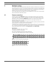
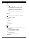
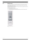
Figure 4.9 Alarm input connector for 16-channel model
Figure 4.10 Alarm input connector for 8-channel model
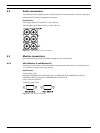
Figure 4.11 Alarm output connector
DANGER!
Electrical voltage.
Risk of electric shock and damage to the unit.
The contacts must not be used at AC line voltages.