


Digital Video Recorder 440/480 Series Hardware setup | en 21
Bosch Security Systems Installation and Operation manual AM18-Q0605 | v2.0 | 2012.04
4 Hardware setup
This chapter contains detailed information about the hardware installation and connection of
external equipment to the unit. The connector types and their pin signals are described. Most
of the connectors are located at the rear panel of the unit. For convenience, one USB port is
located on the front of the unit to connect a mouse or memory device.
All the input/output ports are Safety Extra Low Voltage (SELV) circuits. SELV circuits should
only be connected to other SELV circuits.
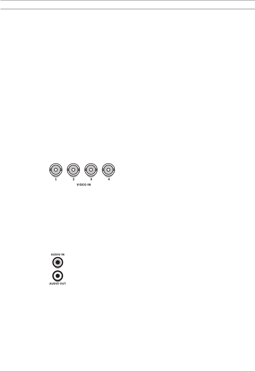
4.1 Camera connections
Connect cameras to the VIDEO IN connectors on the back of the unit using 75 ohm video
coaxial cables with BNC connectors.
The unit automatically configures itself as a PAL or NTSC unit. The unit determines the
standard by detecting the signal format of the VIDEO IN 1 during startup. The unit can also be
manually set to PAL or NTSC in the ‘Camera menu’ under ‘Video format’.
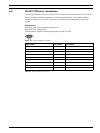
Specifications
Input signal: Composite video 1 Vpp, 75 ohm
Color standard: PAL/NTSC, auto-detect
Gain control: Automatic gain control for each video input
Connector type: BNC
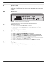
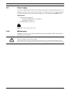
Figure 4.1 Camera video inputs - 4 channels
4.2 Audio connections
The unit has 1 audio input and 1 audio output. Connect using audio cable with RCA (CINCH)
compatible connectors.
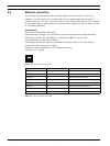
Specifications
Input signal: Mono RCA (CINCH), 1 Vpp, 10k ohm
Output signal: Mono RCA (CINCH), 1 Vpp, 10k ohm
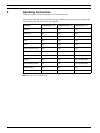
Figure 4.2 Audio output and input connectors