


5.7 Data Output Connection
The LTC 8786 Series provides sixteen biphase control code
outputs. Connect a shielded twisted-pair cable (BELDEN
8760 or equivalent) from a biphase control code output of the
converter unit to the camera site. Typically, a single camera
site receiver/driver or AutoDome is connected, but the
biphase output of the converter unit is rated to handle up to
8 devices when connected in a daisy chain configuration to a
maximum of 1.5 km (5000 ft). For a daisy chain connection,
the cable is looped through each AutoDome camera or
receiver/driver along the way. Only the last unit in the daisy
chain connection should be terminated. All other
receiver/drivers should have their terminating resistor
removed when the looping cable is connected.
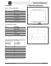
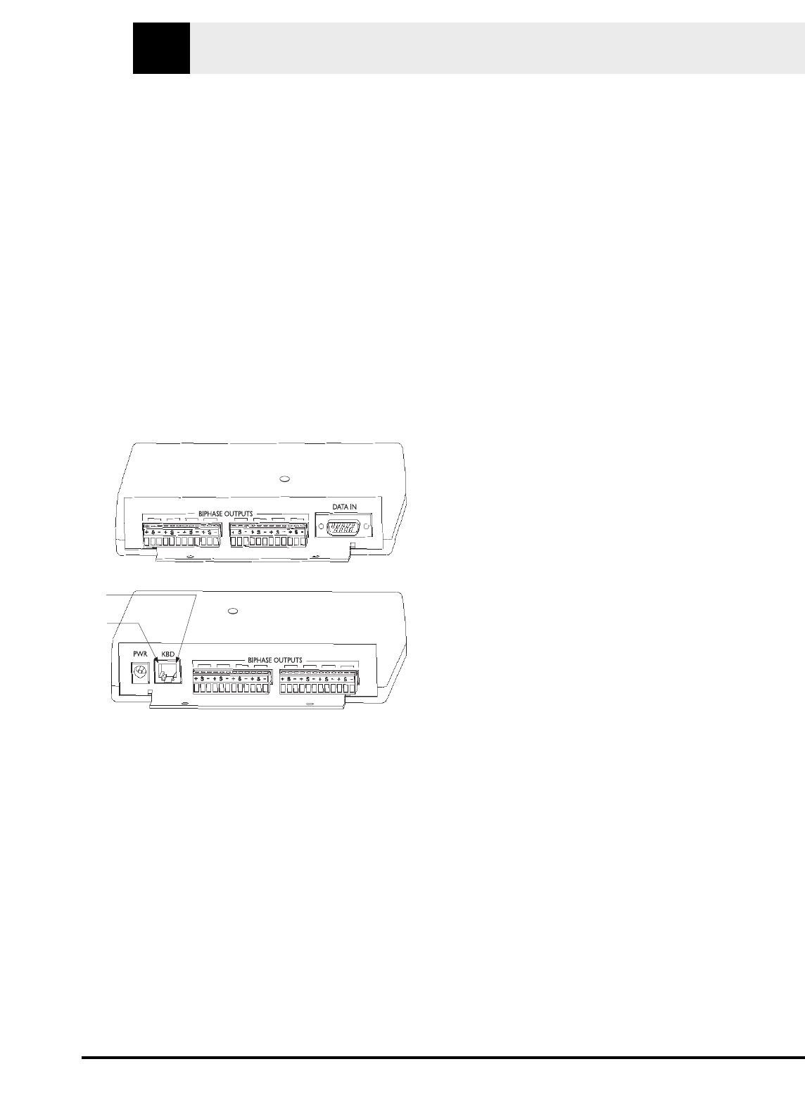
The removable terminal blocks for the biphase code outputs
have three connections: (+), (S) (Shield), and (–) for each of
the sixteen biphase code outputs as shown in FIGURE 1.
Figure 1 LTC 8786 Data Converter Connections
Select and maintain a wire color convention to avoid confu-
sion at the camera site(s).
Example: White to (+), (Shield) to (S), and Black to (–).
NOTE The shield terminal of the interface unit is connected
to the shield wire of the cable.
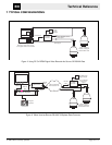
5.8 AutoDome Camera or
Receiver/Driver Site Configuration
Follow the standard installation instructions provided with
the AutoDome Camera or Allegiant Series Receiver/Driver
unit for setting device address and connecting the data cable
to the unit.
Video signals from the camera site are NOT associated with
this product. The video signal(s) from the camera site(s)
should be connected to an appropriate viewing monitor or
other video processing equipment (switcher, PC video capture
card, etc.).
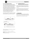
6OPERATION
Operation of the LTC 8786 Series is automatic. An LED, visi-
ble on the top cover of the unit, will flash to indicate that the
unit has converted RS-232 data into biphase control code. No
programming or other user adjustments are required.
Operation
EN
© 2003 Bosch Security Systems Page 9 of 12
Pin 1
Pin 6