


BUSH | HD Ready LCD TV | User Manual | Customer Helpline 0845 604 01058
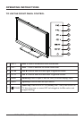
PERIPHERAL CONNECTION GUIDE
AC POWER
26/32
42
42
①
②
③
④
⑤
⑥
①
②
③
④
⑤
⑥
⑮
⑦⑪⑩
⑪
⑧ ⑬
⑧ ⑬
⑨⑭
⑫
⑫
⑭
⑨
⑦⑩
26/32
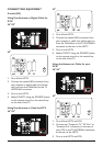
①
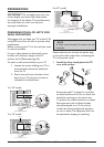
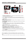
COMMON INTERFACE (CI) – Conditional Access Module (CAM) use only. Please
contact your service provider for details.
②、③、④
AV IN – Connect the primary source for composite video devices, such as a
VCR or video game. Use the white and red connectors to connect the external audio from
the same source.
⑤
USB – Technician service use only.
⑥
Earphone Output – Connect to the headphones. When the headphone is inserted to the
plug, all the speakers will be muted.
⑦
TV ANTENNA – Connect to an antenna or digital cable (out-of-the-wall, not from Cable
Box) for Digital TV.*
⑧、⑬
SCART – Connect the video recorder or decoder to the television. Full SCART
transmits RGB, CVBS video in/out, and audio in/ out; HALF SCART transmits S-Video, CVBS
video in/out, and audio in/ out.
Note : SCART1/2 has monitor out. (CVBS/YPbPr/ATV/DTV)
⑨
PC IN – Connect the video and audio cables from a computer here.
⑩
COMPONENT (Y/Pb/Pr with Audio L/R) – Connect the primary source for
component video devices such as a DVD Player or set top box here.
⑪
SPDIF (Digital Audio Out) – When a digital audio signal is associated with the input
selected for viewing, the digital audio will be available on this SPDIF connection to your
home theatre system.
⑫、⑭、⑮
HDMI – Connect the primary source for digital video such as a DVD multimedia
player or set top box through this all digital connector.
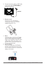
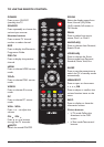
Once your equipment is connected, use the following procedure to view the input signal:
Press the SOURCE button on the remote controller to select the relevant source to view. (ex:
Press
YPbPr button to select “YPbPr” if you have connected a video recorder to Component socket.)