


Installation Instructions
8
2
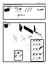
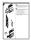
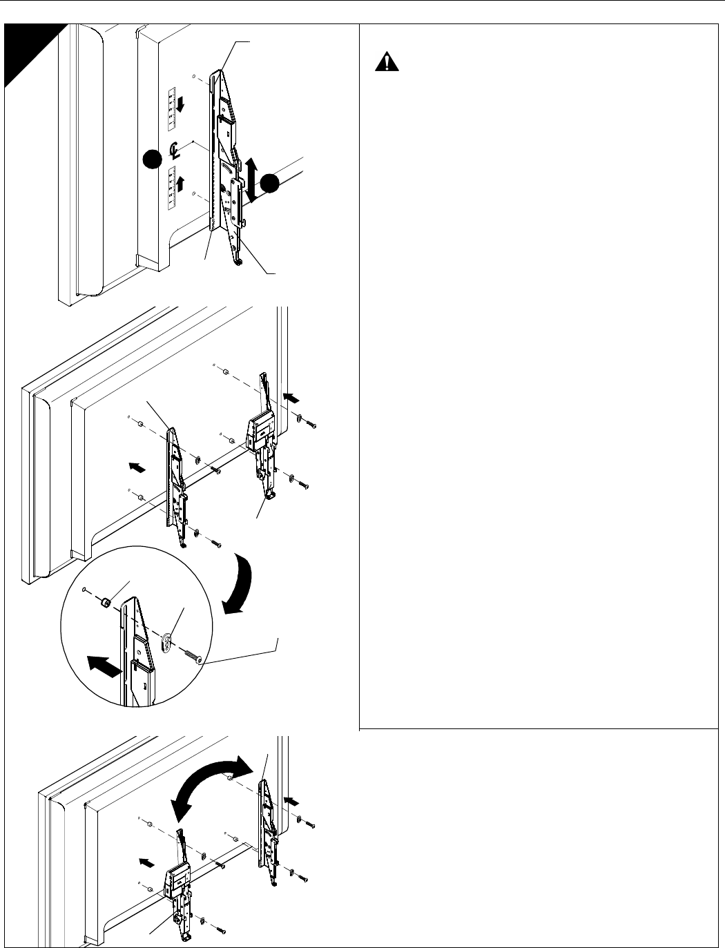
Attaching Brackets to Display
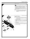
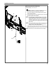
WARNING: IMPROPER INSTALLATION CAN LEAD TO
MOUNT FALLING CAUSING SERIOUS PERSONAL
INJURY OR DAMAGE TO EQUIPMENT! DO NOT substitute
hardware. Only use hardware provided or specified by
manufacturer.
NOTE: Locate Digital Optical Audio Output on back of display
(if available).
1. Determine and mark the vertical center position between
the left side upper and lower mounting holes in display.
2. Determine and mark the vertical center position between
the right side upper and lower mounting holes in display.
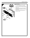
3. Orient non-motorized mounting bracket (C) so that
mounting holes are on bottom and mounting slots are on
top.
4. Align mounting holes and slots in bracket (C) with upper and
lower mounting holes on left side of display.
NOTE: For mounting pattern widths less than 10-1/4", reverse
location of brackets (A) and (C).
5. Adjust mounting bracket (C) position until mark made in
Step 1 aligns with center mark in bracket (C)
NOTE: Vertical center of mounting bracket is at bottom of third
slot.
6. Secure bracket (C) to display using the screws provided
(G1 through G12).
NOTE: Also use universal washers (G15) if using screws (G1
through G8).
NOTE: If the display has a recessed mounting surface,
protrusions or a power box, a spacer and longer
mounting hardware must be placed between the
display and mounting bracket (C).
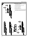
7. Repeat Steps 3 through 6 for motorized mounting bracket
(A) using the same hole locations to align brackets
horizontally.
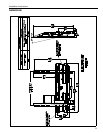
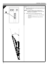
(A)
(C)
(Mounting Pattern Width
less than 10-1/4")
(A)
(G1 through G12)
(G15)
(G13 or G14)
(C)
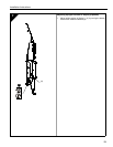
1
Mounting
Slots
Mounting
Holes
(C)
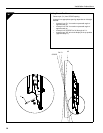
5