


iCMPFM1S/iCMPFM1B Installation Instructions
12
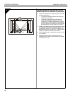
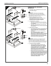
INSTALL BRACKETS TO DISPLAY
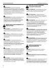
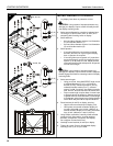
1. Lay display face down on protective surface.
CAUTION: Using screws of improper diameter may
damage your display! Proper screws will easily thread
into display mounting holes.
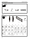
2. Select screw diameter by examining hardware bags
"A" through "D" (8mm, 6mm, 5mm, or 4mm) and
comparing with mounting holes on display.
3. Select washers:
• 6mm and 8mm diameter screws: Use flat washer
(U) and shoulder washer (T).
• 4mm and 5mm diameter screws: Use flat washer
(S) and shoulder washer (R).
4. Select spacers:
• If mounting holes are not recessed, and both
brackets (A and B) can lay flat against display,
then no spacers are required.
• If mounting holes are recessed, or if protrusions
prevent brackets (A and B) from laying flat, then
spacers (V or W) must be used. Select shortest
spacer which will provide adequate fill. All spacers
must be same length.
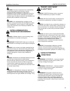
CAUTION: Using screws of improper length may
damage your display! Proper screws will have adequate
thread engagement without contacting bottom of display
mounting holes.
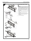
5. Select screw length:
• Using your hand, insert SHORTEST length screw
of selected diameter (E, H, K, or N) through
bracket (A or B), selected flat washer (S or U),
selected shoulder washer (R or T), selected
spacer (V or W, if required), into display mounting
hole. Do NOT thread screw into hole at this time.
• Proper screw length requires base of screw head
to protrude above flat washer a distance equal to
or greater than the screw diameter. If screw length
is inadequate, select longer screw. Select shortest
screw which will protrude the required distance.
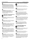
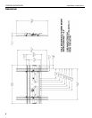
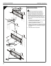
6. Place brackets (A and B) on display, ensuring:
• Upper hooks are towards top of display, and
• Hook plates are towards outside of display for
mounting hole width up to 16-3/4" (425mm), or
towards inside of display for mounting hole width
from 16-3/4" (425mm) to 19-3/4" (501mm).
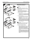
7. Using Phillips screwdriver, carefully install selected
screws through flat washers, shoulder washers,
brackets, and spacers (if required), into display.
Do not tighten screws at this time.
8. Vertically center brackets (A and B) on display.
9. Tighten all screws. Ensure all applicable display
mounting holes (4, 6, or 8) are used.
2
8
9
X4, X6,
2
5
3
3
1
1
7
X4, X6, X8
7
X4, X6, X8
4
V, W
X8
(S, U)
(R, T)
2
5
3
3
(S, U)
(R, T)
6
(A, B) X2
6