Installation Instructions MCD Series
5
INSTALLATION
WARNING: FAILURE TO PROVIDE ADEQUATE
STRUCTURAL STRENGTH FOR THIS COMPONENT CAN
RESULT IN SERIOUS PERSONAL INJURY OR DAMAGE
TO EQUIPMENT! It is the installer’s responsibility to make
sure the structure to which this component is attached can
support five times the combined weight of all equipment.
Reinforce the structure as required before installing the
component.
IMPORTANT ! : These installation instructions assume
that a 1-1/2" NPT or NPSM following ANSI/ASME
B1.20.1 (Schedule 40, 0.154" minimum thickness steel or
aluminum - ASTM B221) threaded extension column (not
included) has been properly installed and is in place.
Attaching Mount to NPT Pipe
CAUTION: Watch for pinch points. Do not place fingers
between moveable parts.
1. Thread the MCD mount (A) onto the existing 1-1/2" NPT or
NPSM pipe (not included) until tight, with a minimum of four
threads engaged. (See Figure 1)
2. Install and tighten the 5/16-18 x 3/8" set screw (B). (See
Figure 1)
Figure 1
Attaching Interface Bracket to Displays
1. Attach MSBU or MSBV interface bracket to displays
following instructions included with MSBU/MSBV interface
bracket kit.
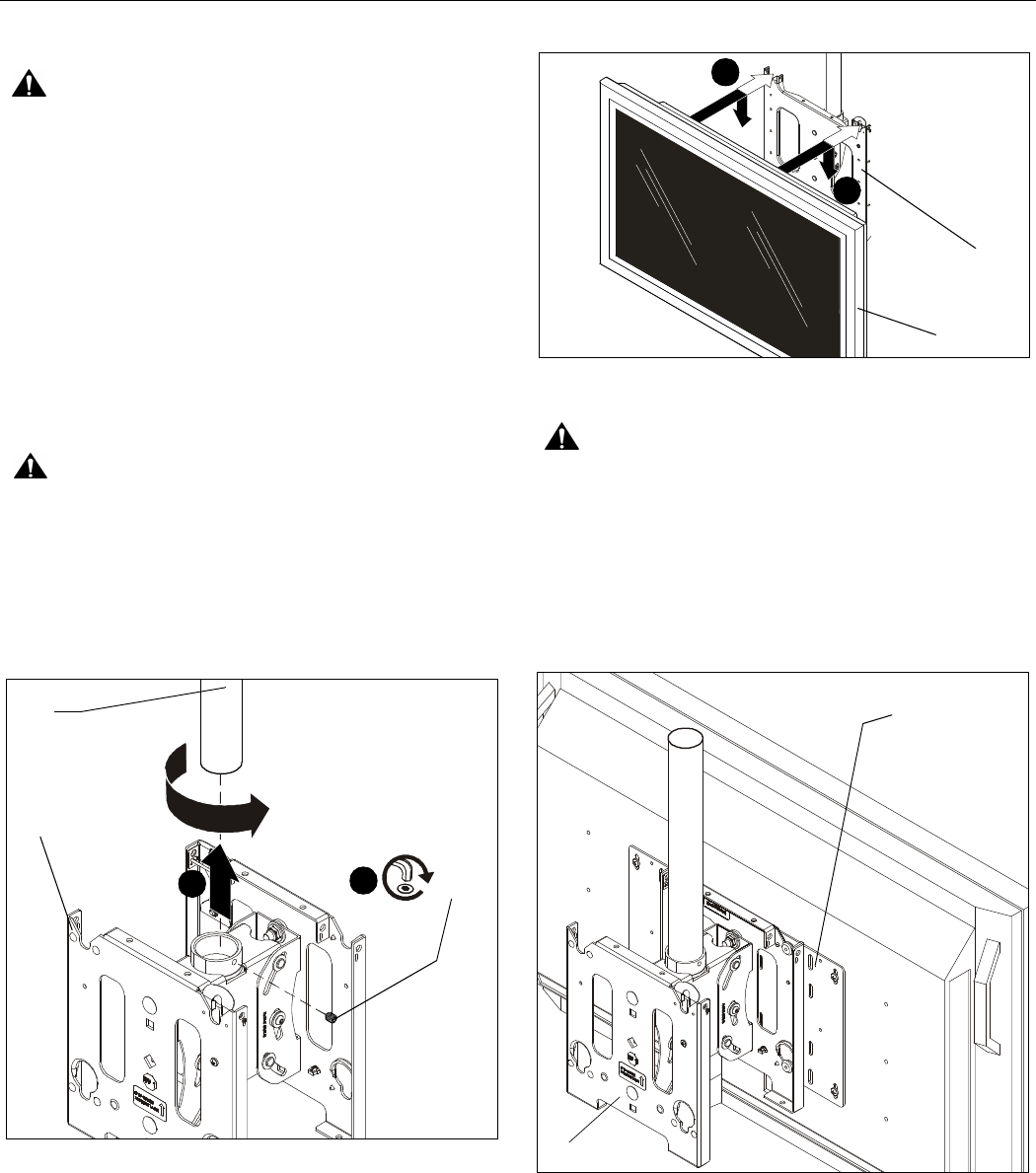
Attaching Displays to Mount
1. While supporting both sides of display, align four mounting
buttons on interface bracket with four mounting holes in
mount. (See Figures 2, 3 and 4)
Figure 2
WARNING:
DISPLAY MAY WEIGH IN EXCESS OF 40 LBS!
Always use two people and proper lifting techniques when
installing or positioning display on mount.
2. Lower display into place listening for audible "click" to
ensure recessed area of mounting buttons are properly
seated in lower area of mounting holes and ClickConnect
mechanism has engaged. (See Fig. 2, 3 and 4)
3. Repeat Steps 1 and 2 for second display.
Figure 3
(A)
NPT
Pipe
2
1
(B) x 1
1
(A)
Display
2
(A)
Back
of Display
MSBV interface
bracket
(example only)


