


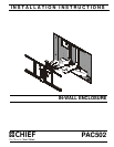
Installation Instructions PAC502
5
INSTALLATION
WARNING: IMPROPER INSTALLATION CAN RESULT IN
DEATH OR SERIOUS PERSONAL INJURY! This accessory
should be installed by qualified personnel.
Site Preparation
Locate and Prepare Mounting Site
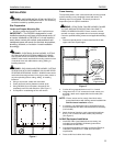
1. Identify a suitable wall location for the in-wall enclosure.
IMPORTANT ! : The PAC502 is designed for in-wall
installation spanning a minimum of three wood studs, 16"
on center. Installation of PAC502 in 2 x 4 wall results in
nearly direct contact with vertical studs and back wall.
Inadequate space will remain for electrical wires/cables,
plumbing, ductwork, or insulation. Locate installation
accordingly.
WARNING: ELECTRICAL SHOCK HAZARD! CUTTING
OR DRILLING INTO ELECTRICAL WIRES OR CABLES
CAN CAUSE DEATH OR SERIOUS PERSONAL INJURY!
ALWAYS make certain area behind mounting surfaces is free
of electrical wires and cables before cutting, drilling, or
installing fasteners.
WARNING: EXPLOSION AND FIRE HAZARD! CUTTING
OR DRILLING INTO GAS PLUMBING CAN CAUSE DEATH
OR SERIOUS PERSONAL INJURY! ALWAYS make certain
area behind mounting surfaces is free of gas, water, waste, or
any other plumbing before cutting, drilling, or installing
fasteners.
2. Using a stud sensor, locate and mark studs.
3. Center and level housing between marked studs.
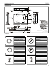
4. Using PAC502 (A) as a template, draw pencil line
completely around in-wall enclosure. (See Figure 1)
5. Cut drywall on outside edge of line and remove.
Figure 1
Frame Housing
The exposed portion of the center wood stud must be removed
and the resulting cavity completely framed with wood. The
following steps are suggested. The actual procedure is
dependent upon the specific installation.
WARNING: STRUCTURAL FAILURE HAZARD! FAILURE
TO TAKE ADEQUATE PRECAUTIONS CAN LEAD TO
DEATH OR SERIOUS INJURY! Ensure removal of center
stud will not cause unacceptable loss of structural strength.
Consult a qualified building contractor and applicable building
codes.
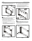
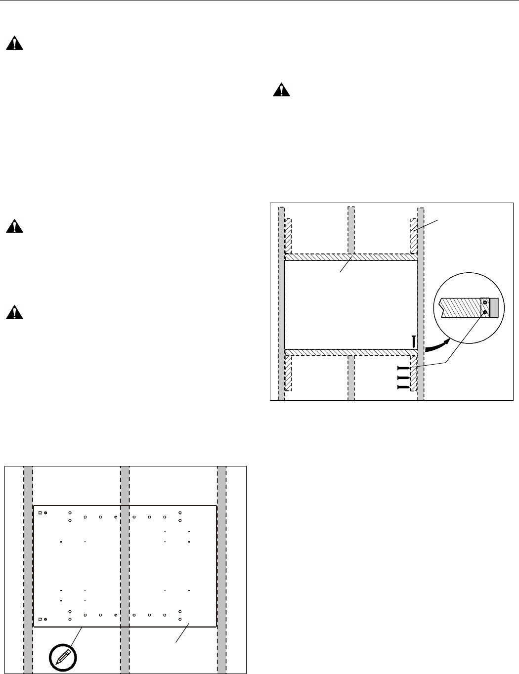
1. Remove exposed portion of center wood stud flush with
upper and lower drywall edges.
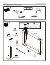
Figure 2
2. Cut four 8" long support blocks out of 2" x 4" wood.
3. Using three #10 x 2-1/2" countersunk wood screws (not
provided), attach each support block to the studs (See
Figure 2)
NOTE: Ensure screws are far enough from block end to
prevent interference with framing screws installed in In-
Wall Enclosure Installation section.
4. If necessary, cut rectangular hole in horizontal framing to
accommodate the PAC-GB1 Listed electrical box accessory
(not included).
5. Attach horizontal framing to each support block with two
#10 x 2-1/2" countersunk wood screws (not provided).
(See Figure 2)
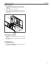
In-Wall Enclosure Installation
1. Install PAC-GB1 Listed electrical box accessory (not
included) into the PAC502 (A) following instructions
included with the PAC-GB1.
2. Connect electrical wiring according to National Electrical
Code(NEC) ANSI/NFPA 70 - 2008, wire connection
requirements.
3. Route audio/visual cables into housing.
Wood Studs
(A)
Horizontal Framing
Support
Blocks
Top View
Wood
Screws
(5 places)
(Typical for each
support block)