


PAC516 Installation Instructions
6
WARNING: ELECTRICAL SHOCK HAZARD! CUTTING
OR DRILLING INTO ELECTRICAL WIRES OR CABLES
CAN CAUSE DEATH OR SERIOUS PERSONAL INJURY!
ALWAYS make certain area behind mounting surfaces is free
of electrical wires and cables before cutting, drilling, or
installing fasteners.
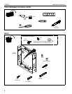
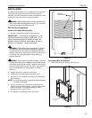
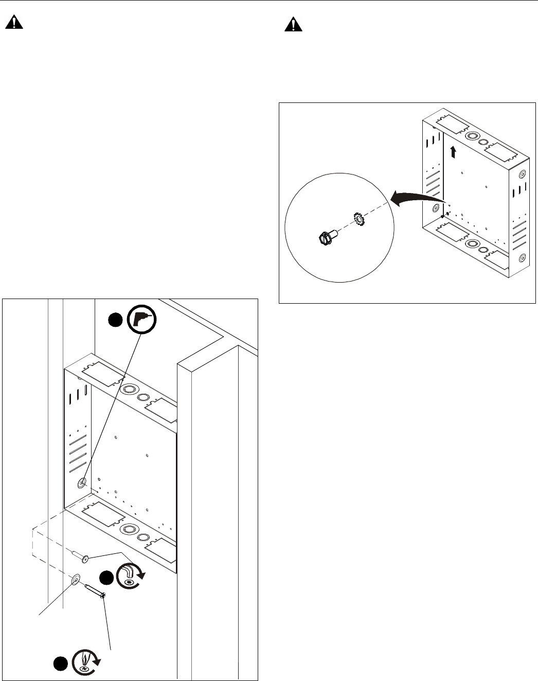
2. Secure accessory box to studs by:
WOOD STUD:
1. Drill four 3/16" dia. pilot holes in studs at mounting
holes. (See Figure 3)
2. Install four M7 x 40mm Allen head connector screws
(F) into pilot holes using an M4 Allen head drill bit
(D). (See Figure 3)
STEEL STUD:
1. Drill four 3/16" dia. pilot holes in studs at mounting
holes. (See Figure 3)
2. Install four 1/4" countersunk finishing washers (B)
and four 1/4" x 2" Phillips flat head self drilling
screws (G) into pilot holes. (See Figure 3)
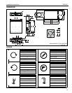
Figure 3
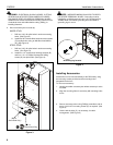
DANGER: IMPROPER WIRING CAN LEAD TO DEATH
OR SEVERE PERSONAL INJURY! Grounding must be
installed by qualified personnel using a UL Recognized No.
12AWG Green and Yellow grounding wire connected to
grounding lug on mount.
Figure 4
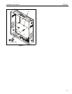
Installing Accessories
Accessories can be mounted directly to the PAC516 by using
the mounting screws provided and the mounting holes
integrated into the box.
To mount an accessory:
1. Identify area within accessory box where accessory is to be
mounted.
2. Align the mounting holes in accessory with mounting holes
in box.
3. Secure accessory to box using Phillips screwdriver and as
many 1/8-18 x 3/4" mounting screws (E) as required. (See
Figure 5)
4. Use the wire tie clips (C), as necessary, for cable
management. (See Figure 5)
x 4
(Steel Stud Only)
(Steel Stud Only)
(B) x 4
(G) x 4
(F) x 4
1
2
2
2
1
Grounding lug location
Typical