10
Cisco Aironet 14-dBi Vertically Polarized Sector Antenna (AIR-ANT2414S-R)
78-16403-01
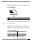
When you are using LEDs to maximize the signal, adjust the antenna until as many LEDs as possible are
on and the rest are blinking as fast as possible. With all three LEDS on, the signal is good enough to
support the maximum data rate.
To position the antenna using the LED indicators, follow these steps:
Step 1 Verify that the Install LED is either continuous amber or green.
Step 2 Slowly pan the bridge to the left and right of the signal path, and watch for peaks in signal strength. Be
sure to swing the antenna in an arc of 45 degrees to each side to ensure that the passes through the
strongest signal level.
Step 3 Return the bridge to the position where the signal is strongest.
Step 4 Secure the horizontal adjustment by tightening the hex head bolts on the antenna bracket. Tighten the
nuts wrench tight. Do not overtighten.
Step 5 Slowly tilt the antenna, and watch for a peak in signal strength. Use the full vertical adjustment range of
the mounting brackets.
Step 6 Return the bridge to the position where the signal is strongest, normally where all signal strength LEDs
are on. If you are unable to turn on all LEDs, simply maximize the signal.
Step 7 Secure the vertical adjustment by tightening the nuts that secure the adjustable antenna bracket to the
mast mount clamp plate wrench tight. Do not overtighten.
Grounding the Antenna
Follow these steps to ground the antenna in accordance with national electrical code instructions.
Step 1 Use No. 10 AWG copper or No. 8 or larger copper-clad steel or bronze wire as ground wires for both
mast and lead-in. Securely clamp the wire to the bottom of the mast.
Step 2 Secure the lead-in wire to an antenna discharge unit and the mast ground wire to the building with
stand-off insulators spaced from 4 ft (1.2 m) to 8 ft (2.4 m) apart.
Step 3 Mount the antenna discharge unit as close as possible to where the lead-in wire enters the building.
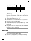
–60 to –57 Off Medium blink On
–63 to –60 Off Slow blink On
–66 to –63 Off Off On
–69 to –66 Off Off Fast blink
–72 to –69 Off Off Medium blink
–75 to –72 Off Off Slow blink
–75 or weaker Off Off Off
1. Blinks once per second.
2. Blinks twice per second.
3. Blinks four times per second.
Table 1 Install Mode RSSI Display (Continued)
Signal Level (dBm) Ethernet LED Status LED Radio LED


