CRESTRON CNTV Cresnet Television Control Unit
REMOTE CONTROL SYSTEMS
3 DOC. 8105B
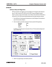
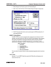
The ports are preconfigured by Crestron to determine which of the following functions each port performs.
The serial ports are capable of several different functions.
1. Connection of wired control panel (MRWP or MRWPLCD).
2. Connection to a classroom computer running Crestron's IBM Linkway interface, Crestron's Course
Director software, or Crestron's MacIntosh Transmitter software.
Indicators
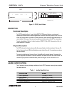
There are five LED indicators located on the front panel of the CNTV.
IR
This red LED turns "on" when an IR signal from the hand transmitter is received by the CNTV.
MESSAGE
This red LED "lights" when a message has been sent to the classroom in which the unit resides. To turn
"off" the LED, depress the Message button on the transmitter (MRHC) or wired panel (MRWP or
MRWPLCD).
READY
This red LED "lights" when sources have been scheduled and are active for the classroom in which the
unit resides.
T and R
These two red LEDs "light" or flash rapidly when there is communication between the associated control
system and the CNTV. The LEDs should illuminate when power is supplied to the CNTV.
INSTALLATION/SETUP:
Optional Equipment
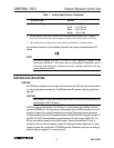
Due to variations in installation requirements, not all possible peripheral pieces of equipment are supplied
with the CNTV. Table 2 provides a list of all optional equipment that can be used in conjunction with the
CNTV.
Table 2. Optional Equipment
EQUIPMENT PART NUMBER MANUFACTURER RATIONALE
Wall Jack 048-0059-ND Digi-Key Provides interface to Cresnet system.
RJ11 (6-position, 6-pin)
modular telephone
connector cable
Consult catalog
regarding application
requirements.
Digi-Key Provides connection to Cresnet system.


