


-6-
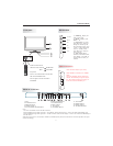
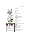
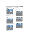
Front panel
INSTALLATION
1 2 3
4 5 6
7 8 9 0
+
CH
_
+
_
VOL
1: Remotecontrol sensor.
2: IndicatorLED: GREEN POWER ON.
RED STANDBY.
3: Keyboard
4: Power: Press thisbutton to turn theunit
ON from STANDBYmode.
Press it again to turnthe set back to
STANDBY.
30 30
1
3
4
2
SOURCE
MENU
CH+
CH-
VOL+
VOL-
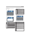
KEYBOARD
1 SOURCE Display the
input source menu.
CH+ or CH- to select
items .
press CH+ or CH- to
press VOL+ or VOL-
to
2MENUD
3 CH+/CH-:
4 VOL+/VOL-:
isplay main
MENU.
In TV mode
press CH+ or CH- to
change the channel up and
down.In MENU mode, press
In standby mode,
turn on the TV.
Adjust
sound level.In MENU mode,
adjust the item that you
selected.
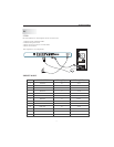
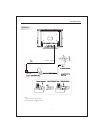
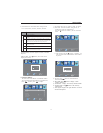
REAR AV Connection
Note:
1.AV1 and S-VIDEO1 share oneaudio channel.
2. WhenHDMI1 port get DVI signal, the PCAudio channel will change to receive the audio from HDMI1 port
3. WhenHDMI2 port get DVI signal, the YPbPr Audio channel will change to receive the audio fromHDMI2 port.
4.AV OUTPUT:
When the source areAV1,AV2(side) S-VIDEO1,S-VIDEO2(side),ATV,theAV OUTPUT Channelreproduce the input
signals accordingly
1.ANT
2.AUDIO OUTPUT
3. OUTPUT
4. VIDEOOUTPUT
5.AV1/S-VIDEO1AUDIO INPUT
SPDIF
11. VGAINPUT
12. HDMI2 INPUT
13. HDMI1 INPUT
14.AC POWER INPUT
12 45678 9
10
11
12
13
143
6.YPbPrAUDIO INPUT
7. PCAUDIO INPUT
8.YPbPr INPUT
9. AV1 INPUT
10. S-VIDEO1 INPUT
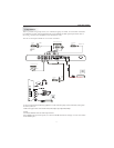
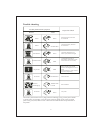
SIDE PANEL(LEFT)
HEADPHONE
S-VIDEO2
VIDEO
L
R
HDMI3
AV2
NOTE:
AV2 and S-VIDEO2 share the audio input
channel. When HDMI3 port get DVI signal,
the AV2 Audio channel will change to
receive the audio from HDMI3 port.
All the terminals are(from up to down):
HEAD PHONE, S-VIDEO2, AV2, HDMI3.