


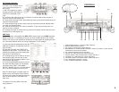

Power and Speaker Connections (Refer to Wiring Diagram on page 5.)
A-Main Power-Red Wire B+
Connect the RED wire (B+) to an accessory fuse that is switched OFF when
the key switch is in the OFF position and is switched ON when the key switch
is switched to the ON or accessory position. (This does not apply to cars
with 6volt system)
B-Memory Back-Up-Orange Wire B+
Connect the orange wire (memory B+) to an accessory fuse that is always
ON regardless of the position of the key switch.The lead supplies power to the
program memory and the clock circuit when the USA-630 is switched off.(This
does not apply to cars with 6volt system)
C-Power Antenna (Auto-Antenna) - Yellow Wire
This wire can be connected to the positive switch terminal of the relay for the
auto antenna (if your car is equipped )or to the remote on switch of the ampli-
fier or booster (if equipped). NOTE:DO NOT connect this wire to a negative
position or to any device that requires high current Otherwise the radio may
fail or become "fried". If your car is not equipped with an auto antenna,leave
this wire sealed and do not allow it to short to any other positions.
D - Ground Wire - Black
Connect the black ground wire to any clean paint and contaminant free area
of vehicle chassis.
NOTE: Proper grounding is essential for optimum performance of your radio.
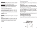
E - Speaker Wires
Connect the speaker wires as shown in Figure 1.
Low Level Output (Line Out Jacks) Connection
The USA-630 is equipped with low level, high impedance outputs. The low
level outputs (RCA type Line Out Jack) will not drive speakers. If you are con-
necting an amplifier or plan on it in the future, it is recommended to use these
leads. It makes for a cleaner and easier Installation.
4
11
Noise Suppression
All CAM Systems are designed for maximum electrical noise rejection. In some instal-
lations however, electrical noise may affect the quality of sound reproduction.
If noise is present after installing the USA-630, identify the source of the noise using
the descriptions under Sources Of Electrical Noise. To eliminate the noise follow the
procedures described under Elimination of the specific noise source.
Noise Suppression
1-Check all ground connections. Remove paint from painted surfaces to secure a
. good electrical ground.
2-Check battery posts. If contacts are corroded or loose, clean and tighten both
. terminals.
3-Check battery or add fluid.
4-Check condition of spark plug and distributor leads. Worn or damaged leads will
. generate noise than can be very difficult to eliminate.
5-Check installation of factory noise suppressor(s). Verify that the connections are
. .
. solid. Refer to the vehicles service manual for nose suppressor location or allow a .
. qualified mechanic to inspect the device(s) for you.
6-(Optional) Some professional installers will install a simple L.C. noise filter even if
. .
. there is no noise present in the system. This is a simple and relatively inexpensive .
. device available at your nearest Autosound dealer or electronic supply store. Most .
. filters designed for car stereos carry a current rating of 3 amps or more. Follow the .
.
manufacturers installation instructions. This filter is installed in the power lines of the
. car stereo.
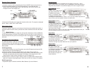
Sources Of Electrical Noise
Alternator Noise
This noise is generally a high pitch whine present with the engine running.The pitch of
the whine will vary as engine RPM varies. Alternator noise usually becomes more
apparent with an electrical load to the system. Switching the headlights on usually
increases the noise.
Elimination
1. Install an L.C.noise filter (available from your Autosound dealer or your nearby .
electronic or automotive supply store) in the power lines of your USA-630. This filter . .
should be rated at 3 amps minimum.
2. Start the car’ s engine.switch on the lights (to accentuate the noise) and switch . .
on the USA-630. If noise is still present, proceed to step 3.
3. Install an alternator noise filter (available from your Autosound dealer or your
. . .
nearby electronic or automotive supply store). Follow manufacturer’ s installation .
. instructions.
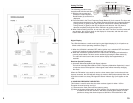
Antenna
Input
USB
Input
CD Changer
iCAMKIT
Input
AUX
Input
Line - Out
Front
Line - Out
Rear
Fuse
Box
RL R
L
L
R