


-3-
SAFETY PRECAUTIONS
CAUTION : Do not attempt to modify this product in any way. Unau-
thorized modifications will not only void the warranty, but may lead to your
being liable for any resulting property damage or user injury.
Service work should be performed only after you are thoroughly familiar
with all of the following safety checks and servicing guide-lines. To do
otherwise, increases the risk of potential hazards and injury to the user.
SAFETY CHECKS
After the original service problem has been corrected, a check should be
made of the following:
SUBJECT : FIRE & SHOCK HAZARD
1. Be sure that all components are positioned in such a way as to avoid
possibility of adjacent component shorts. This is especially important on
those chassis which are transported to and from the repair shop.
2. Never release a repair unless all protective devices such as insula-tors,
barriers, covers, shields, strain reliefs, and other hardware have been
reinstalled per original design.
3. Soldering must be inspected to discover possible cold solder joints,
frayed leads, damaged insulation (including A.C. cord), solder splashes
or sharp solder points. Be certain to remove all loose for-eign particals.
4. Check for physical evidence of damage or deterioration to parts and
components, and replace if necessary follow original layout, lead length
and dress.
5. No leads or components should touch a receiving tube or a resistor
rated at 1 watt or more. Lead tension around protruding metal sur-faces
must be avoided.
6. All critical components such as fuses, flameproof resistors, capaci-tors,
etc. must be replaced with exact factory types. Do not use replacement
components other than those specified or make unrecommended circuit
modifications.
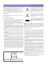
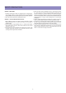
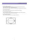
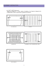
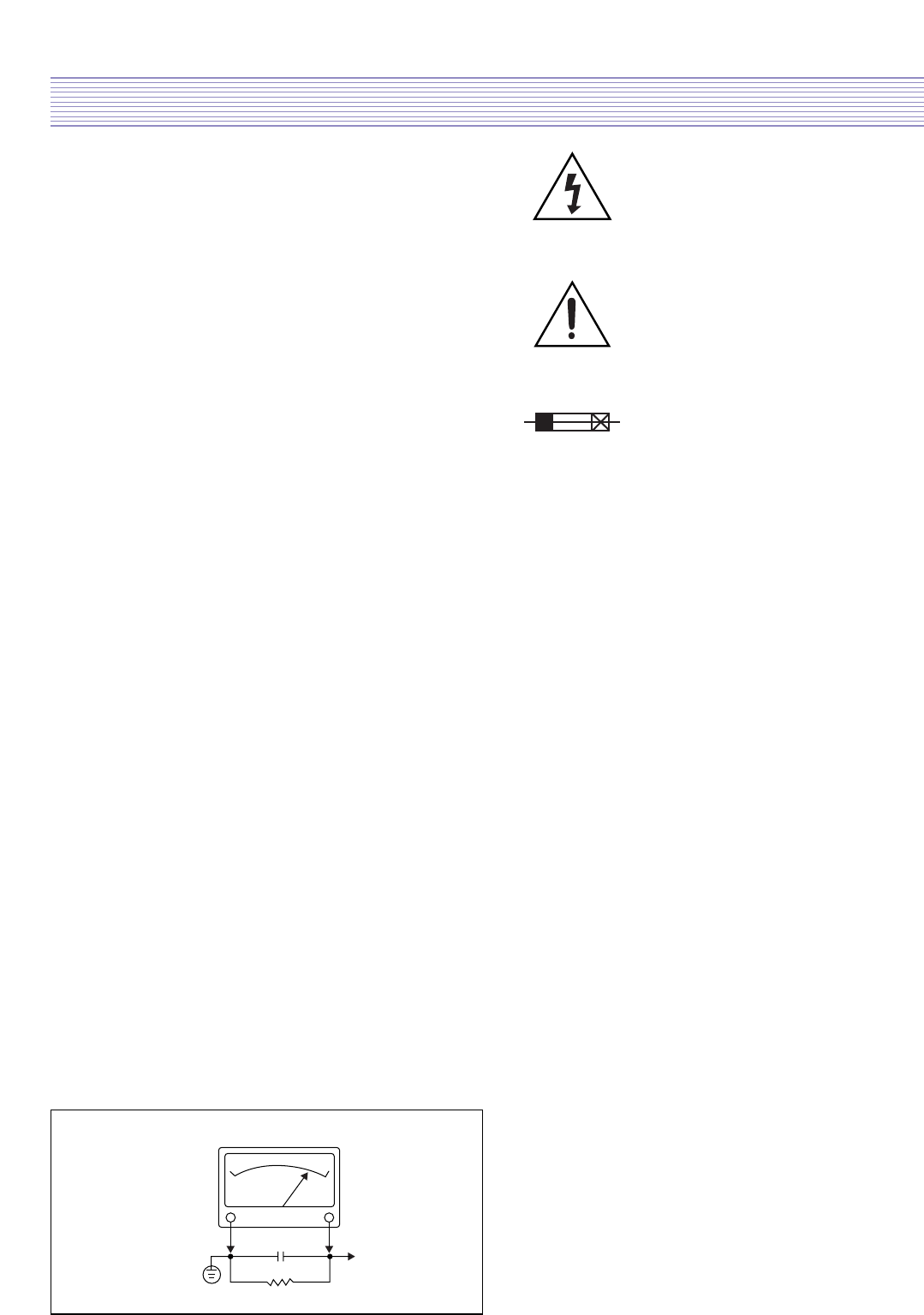
7. After re-assembly of the set always perform an A.C. leakage test on all
exposed metallic parts of the cabinet, (the channel selector knob,
antenna terminals, handle and screws) to be sure the set is safe to
operate without danger of electrical shock. Do not use a line isolation
transformer during this test. Use an A.C. voltmeter, having 5000 ohms
per volt or more sensitivity, in the following manner : connect a 1500
ohm 10 watt resistor, paralleled by a 15 mfd. 150V A.C. type capacitor
between a known good earth ground (9water pipe, conduit, etc.) and
the exposed metallic parts, one at a time. Measure the A.C. voltage
across the combination of 1500 ohm resistor and 0.15 MFD capacitor.
Reverse the A.C. plug and repeat A.C. voltage measurements for each
exposed metallic part. Voltage measured must not exceed 0.75 volts
R.M.S. This corresponds to 0.5 milliamp A.C. Any value exceeding this
limit constitutes a potential shock hazard and must be corrected imme-
diately.
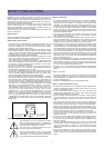
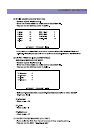
The lightning flash with arrowhead symbol,
within an equilateral triangle, is intended to alert
the service personnel to the presence of uninsu-
lated “dangerous voltage” that may be of suffi-
cienty magnitude to constitute a risk of electric
shock.
The exclamation point within an equilateral tri-
angle is intended to alert the service personnel
to the presence of important safety information
in service literature.
Fuse symbol is printed on pcb adjacent to the
fuse, with “RISK OF FIRE REPLACE FUSE AS
MARKED”. The symbol is explained in the ser-
vice manual with the following wording or equiv-
alent.
CAUTION : FOR CONTINUED PROTECTION AGAINST FIRE
HAZARD, REPLACE ONLY WITH SAME TYPE (5A, 250V)” and
ATTENTION: AFIN D’ASSU UNE PROTECTION PERMANENTE
CONTRE LES RISQUES D’INCENDIE, REMPLACER UNIQUE-MENT
PAR UN FUSIBLE DE MEME TYPE ET DE “5A, 250V”.
SUBJECT : X-RADIATION
1. Be sure procedures and instructions to all service personnel cover
the subject of X-rays in current T.V. receivers is the picture tube.
However, this tube does not emit X-rays when the high voltage is at
the factory specified level. The proper value is given in the appli-
cable schematic. Operation at higher voltages may cause a failure
of the picture tube or high voltage supply and, under certain cir-
cumstances, may produce radiation in excess of desirable levels.
2. Only factory specified C.R.T. anode connectors must be used.
Degaussing shields also serve as X-ray shield in color sets. Always
re-install them.
3. It is essential that the serviceman has available an accurate and
reliable high voltage meter. The calibration of the meter should be
checked perio - dically against a reference standard. Such as the
one available at your distributor.
4. When the high voltage circuitry is operating properly there is no
possibility of an X-radiation problem. Every time a color chassis is
serviced, the brightness should be run up and down while monitor-
ing the high voltage with a meter to be certain that the high voltage
does not exceed the specified value and that it is regulating cor-
rectly. We suggest that you and your service organization review
test procedures so that voltage regulation is always checked as a
standard servicing procedure. And that the high voltage reading be
recorded on each customer’s invoice.
5. When troubleshooting and making test measurements in a receiver
with a problem of excessive high voltage, avoid being unnecessarily
close to the picture tub eand the high voltage compartment. Do not
operate the chassis longer than is necessary to locate the cause of
excessive voltage.
6. Refer to HV, B+and Shutdown adjustment procedures described in
the appropriate schematic and diagrams(where used).
10WATT
GOOD EARTH GROUND
SUCH AS THE WATER
PIPE, CONDUIT, ETC.
1500 OHM
A.C. VOLTMETER
PLACE THIS PROBE
ON EACH EXPOSED
METAL PART
0.15 uF