- 50 -
Service manual WP 895/895F, CP885/885F
configuration
Stand by TV ON
1 Power Push Pull Low Push Pull High Switch OFF / ON SMPS
2 AGC High impedance High impedance Tuner AGC level input –
For factory use only
5 Mod SW High impedance Push Pull High = Negative
modulation, Low = Positive
modulation (L/L’).
6 SECAM L’ High impedance Push Pull Low = L, High =L’
7 AFC High impedance High impedance ADC input
8 IR High impedance High impedance Interrupt input
9 SC1 SW High impedance High impedance SCART 1 slow switching –
ADC input
10 SC2 SW High impedance High impedance SCART 2 slow switching –
ADC input
61 Mute Push Pull Push Pull High = Mute active
62 LED Open Drain Open Drain
63 KB High impedance High impedance Keyboard input – ADC
input
64 OCP High impedance High impedance Over Current Protection –
Switch the set to Std by if < 2.
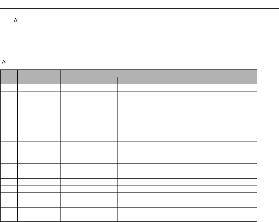
5-4-3 - Controller I/O pin configuration and function
There exist different kinds of ports. The universal ports serve as digital I/O and have additional special input and output
functions. A subset of the universal ports serves as input for the analogue-to-digital converter.
- Controller I/O pin configuration and function table
pin
name
description
To reduce power consumption in stand by mode all ports not used are configured in high impedance mode.
5-4-4 Tuning
The AFC information is supplied by the demodulator IC, and becomes available on VCT pin 7 for controlling software.
The controlling software uses this information for tuner frequency tracking ( automatic following ). The AFC window
is typically between 50 KHz and 100 KHz.
The minimum frequency step of the tuner is 50 Khz.
This AFC function is disabled when a program is tuned using the direct frequency entry or after fine tuning adjustment.
Therefore it is recommended to tune channel with the TV search function ( manual or ATSS ) or using the direct
channel entry to enable the Automatic Frequency Control.
5-4-5 Automatic Format switching and WSS
When AUTO mode is selected by the user, the television will automatically select a mode for the user. The format
information is supplied by SCART pin 8 level when in AV mode or by WSS data. The signal contains codes as defined in
the WSS European Telecommunication Standard, ETS 300 294. Briefly, the signal is received at the beginning of line


