


signals to improve the S/N ratio for a substantially richer dynamic range.
Since the DVD-5000 is equipped with an HDCD decoder, the
Peak Extension and Low-level Extension features are accessed
and combined with Denon’s own 96 kHz, 24-bit 4-DAC
system to fulfill the maximum potential of HDCD's
remarkable sound quality.
The DVD-5000 also automatically senses
the type of disc that has been loaded
(ordinary CD, DVD disc, or HDCD), then
processes the signals based on the type
of disc detected.
■
Independent D/A Converter
The DVD-5000 can also be used as a D/A converter. The
front panel Source switch directs the digital input signals coming in
through one of the two digital input terminals (optical or coaxial) so that it
passes through the unit’s AL24 Processor and D/A converter for output as a clean,
highly accurate analog signal.
■
Color Component Video Output
The DVD-5000 is equipped with a color component signal video output capability that faithfully
outputs the analog signals resulting from direct and high-precision D/A conversion of the Y, Cb and
Cr signals recorded on DVD. “S” and composite video outputs are also provided (2 of each).
■
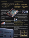
Vibration-resistant Construction
The DVD-5000 protects the DVD and the transport mechanism
from unwanted vibrations using a centrally located holder with low
center of gravity firmly secured with mechanism brackets to the
unit’s highly rigid, copper-plated chassis. This mechanism is further
isolated from the digital, video and audio circuits which have each
been mounted on their own copper-plated board so that the circuits can be thoroughly protected
from mutual interference and vibrations. The overall chassis of the DVD-5000 is constructed of a
15mm thick aluminum front panel, a double-layered top cover and a quadruple-layered bottom
chassis assembly. All these parts have been secured with vibration-absorbent sintered alloy insula-
tors to produce a construction that is totally protected from both internal and external vibrations.
■
Easy-to-use Graphical User Interface (GUI)
■
Parts Strictly Selected for Sound Quality
Three sepa-
rate transform-
ers have been
employed for the
audio, video, and
control sections. Transformers specially constructed with vibration-
resistant materials are used in the audio and video sections. In addition,
the same strictly-selected parts whose performance has proven to be reliable
during the development of Denon’s S1 series of audio components -- such as the
removable ultra-thick AC power cord; very low ESR electrolytic capacitors, film
capacitors and carbon resistors designed for high sound quality; and the high speed
operational amplifiers selected for highest sound quality -- have gone into the DVD-5000.
■
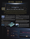
High-performance Pickup and Digital Servo Technology
In order to read the maximum 8.5 gigabytes of data that can be record-
ed on one side of a DVD, the DVD-5000 uses a self-excited oscillator type
red laser with a wavelength of 650nm to ensure stable, low-noise perfor-
mance. In addition, the pickup lens used with this laser employs an integral
molding hologram that enables DVD and CD program sources to be read by
the same pickup. As a result, the DVD-5000 features the shortest possible
signal paths, a simplified construction and superior reliability.
■
Gold-plated Audio and Video Terminals
■
Digital Theater Systems (DTS) Compatible Digital Output
■
Easy-to-use Remote Control with Backlit Keys
■
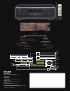
Expanding to Input Signal Bit Length of 24 Bits
While the original ALPHA Processing system generated four lower bits of data for the 16-bit input data
to obtain data of 20-bit quality, the new AL24 Processing uses two calculating circuits in its lower data
generation section to generate eight bits, to which the upper 16 bits of data is then added, producing an
output signal of 24-bit quality (Figure 1).
First of all, the data reproduced from a CD is input “as is” in its 16-bit staircase form to the ALPHA
processor, as shown in waveform (A) of Fig. 2. The processor then extrudes the rate of change in 1 LSB,
whether positive or negative, from the portions of waveform (A) where a change in the data has occurred
and produces waveform (B).
Next, the ALPHA processor uses its lower-
order bit data generator to produce data for
the four lower-order bits, 17-24, that should
normally exist below the 16 bits as shown in
waveform (C). The result is waveform (D),
where lower-order bit data for each 1/16 LSB
point of change is generated.
Finally, the higher-order bits of waveform
(A) are added to waveform (D), producing
the synthesized waveform shown in wave-
form (E). This waveform reflects the smooth
24-bit oversampled data that is reproduced
with superb audio clarity.
Fig.1: AL24 Processor Block Diagram
Fig.2: How AL24 Processing Works on Audio Signals
A. Data generated at higher-order bits (1-16)
B. Extruded rate of change
D. Data added to lower-order bits
E. Total of all data
C. Data generated at lower-order bits (17-24)
Impulse Response
Conventional AL24 Processing
Conventional AL24 Processing
Square Wave
ALPHA Processing and AL24 Processing