


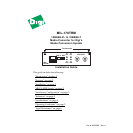

Install Guide
Model: MIL-170TRM 4
The following table shows which Link Sentry feature is enabled:
Note:
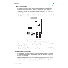
For two MIL-170s used back-to-back and UTP-to-UTP, all DIP switches must be
enabled
(in the “down” position) on the first MIL-170. On the second MIL-170, enable switches 1
and 4 (in the “down” position).
Default setting for Link Sentry: All switches set in the “up” position (disabled). When using
the SNMP module to control the Link Sentry feature, leave the switches in the default
mode (“up”).
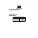
Indicators
There are four LEDs, including:
TP/ACT
: Receiving packets from the 10BASE-T port
TP/LINK
: There is an active connection on the 10BASE-T port
FX/LINK
: There is an active connection on the 10BASE-FL port
FX/ACT
: Receiving packets from the 10BASE-FL port
Specifications
RJ-45: MDI
• Pin 1 = Transmit Data +
• Pin 2 = Transmit Data -
• Pin 3 = Receive Data +
• Pin 6 = Receive Data -
RJ-45: MDI-X
• Pin 1 = Receive Data +
• Pin 2 = Receive Data -
• Pin 3 = Transmit Data +
• Pin 6 = Transmit Data -
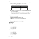
Table 1: Link Sentry Features
Switch Losing Link on RX of Stop sending Link on TX of
1 (down) Fiber port Fiber port
2 (down) UTP port UTP port
3 (down) UTP port Fiber port
4 (down) Fiber port UTP port