


© 2001 Directed Electronics, Inc.
9
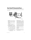
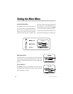
1. VIDEO OUT - Connects to TV video input.
2. VIDEO IN - Connects to a second VCR for
recording or video camera for recording.
3. AUDIO OUT - Connects to receiver or
amplifier input.
4. AUDIO IN - Connects to a second VCR or
an audio source to record audio.
5. Audio Output - Additional audio output.
6. DC (+) 12 VOLT INPUT - To provide power
for the VCR, connect the small plug end of
the power harness on the back of the VCR.
RED: This wire connects to a circuit
that turns on and off with the key.
YELLOW:This wire connects to the battery
or a constant power source.
BLACK: This wire connects to a good
factory ground wire or a metal
part of the chassis.
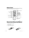
7. REMOTE SENSOR INPUT - The optional
remote infrared (IR) sensor eye allows you
to access all the features on the remote
control when the VCR is mounted in anoth-
er location away from the remote. To install
the remote IR sensor, simply plug it into
the input next to the power plug. Run the
sensor cable to the front of the vehicle and
mount the sensor in a convenient location
so that the remote control can be easily
pointed toward the remote sensor eye.
8. IN FROM ANT - Use to input cable or
antenna signal.
9. OUT TO TV - Use to output VCR signal to
TV or monitor.
Note: Route the wires so they can not be pinched, punc-
tured, or chaffed against bare metal. Always fuse
appropriately at the source.
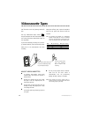
Rear Panel/TV Connection/Power
To connect the VCR and TV, use cable type (A/V RCA-type) appropriate to your TV. Connect the VCR
and TV as shown:
Back of TV
AUDIO IN
On TV
12
9
7
3
6
VIDEO IN
ON TV
Remote IR Sensor
LINE
IN
R
AUDIO
DC 12V
INPUT
REMOTE
SENSOR
INPUT
VIDEO
L
AUDIO
8