


220V Access by Draper page 4 of 4
Wiring Diagrams (continued)
www.draperinc.com
(765) 987-799
9
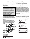
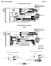
Built-in Video Interface Control
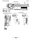
Junction box at
left end of screen
Internal screen wiring
Blue (Neutral)
Black (Hot)
Green/Yellow (Ground)
Dashed wiring
by electrician
220 VAC supply
Trigger signal
VIC220 (220 VAC, white cord & plug)
VIC12 (12 VDC, brown & orange leads)
N
L1
RS232 Data FROM Control System
RS232 Data TO Control System
Signal Ground & Manual Switch Common
Manual Switch Down
Manual Switch Up
Red-to Screen (directional)
Black-to Screen (directional)
Blue-Common
Brown-Hot to 230V AC
Green/Yellow-Ground
Fuse
Program LED
Eye Port for IR Eye. For RF Receiver
or LED Wall Switch, a Splitter and a
Power Supply is required. Plug RF
Receiver or LED Wall Switch and
Power Supply into splitter, then run
cable from Splitter to MC1 Eye Port.
Low Voltage Wiring by others
AC Wiring by electrician
MC1
Terminal strip in
junction box at left
end of screen
230V, 50 Hz.
Neutral
Hot
All-Pole Disconnect
by Others
STOP
Control
Switches
24v DC
STOP
MC1
Built-in Low Voltage Control
Junction box at
left end of screen
Internal screen wiring
Blue (Neutral)
Black (Hot)
Green/Yellow (Ground)
Dashed wiring
by electrician
220 VAC supply
N
L1
See separate Se-
rial Communication-
RS232 Instruction
sheet for enabling
RS232 with the MC1.
Low Voltage and Remote Control
3 Button Wall Switch
DOWN - Black
COM - White
UP - Red
Eye Port for IR Eye, RF Receiver or LED
Switch For more than one of these,
a splitter is required.
Aux Port for connecting additional
LVC-III modules (up to six total-
connect from Aux to Eye).
Red-to screen (directional)
Brown-to screen (directional)
White-Common to screen, 230V AC
Black-to 230V AC
Yellow-to 230V AC
Green-Ground
Dashed wiring by electrician
Low voltage wiring by others
Terminal strip in
junction box at left
end of screen
230V, 50 Hz.
Neutral
Hot
All-Pole Disconnect
by Others
STOP
Control
Switches
24v DC
STOP