


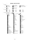
ELECTRICAL ADJUSTMENTS
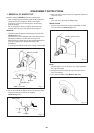
1. BEFORE MAKING ELECTRICAL
ADJUSTMENTS
Read and perform these adjustments when repairing the
circuits or replacing electrical parts or PCB assemblies.
CAUTION
•
•
•
•
Use an isolation transformer when performing any
service on this chassis.
Before removing the anode cap, discharge electricity
because it contains high voltage.
When removing a PCB or related component, after
unfastening or changing a wire, be sure to put the wire
back in its original position.
Inferior silicon grease can damage IC's and transistors.
When replacing IC's and transistors, use only specified
silicon grease (YG6260M).
Remove all old silicon before applying new silicon.
1. Synchro Scope
2. Digital Voltmeter
Prepare the following measurement tools for electrical
adjustments.
2. BASIC ADJUSTMENTS
2-1: RF AGC DELAY
1.
2.
3.
4.
Receive an 80dB monoscope pattern.
Connect the digital voltmeter to TP001.
Activate the adjustment mode display of Fig. 1-1 and
press the channel button (02) on the remote control to
select "RF DELAY".
Press the VOL. UP/DOWN button on the remote control
until the digital voltmeter is 1.80 ± 0.05V.
D1-1
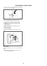
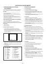
On-Screen Display Adjustment
In the condition of NO indication on the screen.
Press the VOL. DOWN button on the set and the
Channel button (9) on the remote control for more than
1 second to appear the adjustment mode on the screen
as shown in Fig. 1-1.
1.
Fig. 1-1
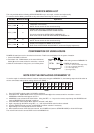
Use the Channel UP/DOWN button or Channel button
(0-9) on the remote control to select the options shown
in Fig. 1-2.
Press the MENU button on the remote control to end
the adjustments.
2.
3.
FUNCTION
OSD H
CUT OFF
RF DELAY
VIF VCO
H VCO
H PHASE
V SIZE
V SHIFT
R DRIVE
B DRIVE
R BIAS
G BIAS
B BIAS
NO.
00
01
02
03
04
05
06
07
08
09
10
11
12
Fig. 1-2
FUNCTION
BRIGHTNESS
CONTRAST
COLOR
TINT
SHARPNESS
FM LEVEL
LEVEL
SEPARATION 1
SEPARATION 2
TEST MONO
TEST STEREO
X-RAY TEST
NO.
13
14
15
16
17
18
19
20
21
22
23
24
TV
00 OSD 15
Adjust the unit to the following settings.
R.DRIVE=10, B.DRIVE=10, R.BIAS=64, G.BIAS=64,
B.BIAS=64, BRIGHTNESS=126, CONTRAST=100.
Place the set with Aging Test for more than 15 minutes.
Activate the adjustment mode display of Fig. 1-1 and
press the channel button (01) on the remote control to
select "CUT OFF".
Adjust the Screen Volume until a dim raster is obtained.
2-2: CUT OFF
1.
2.
3.
4.
2-5: SUB TINT/SUB COLOR
1.
2.
3.
4.
5.
6.
7.
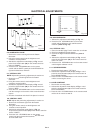
Receive the color bar pattern.
Connect the synchro scope to TP023.
Activate the adjustment mode display of Fig. 1-1 and
press the channel button (16) on the remote control to
select "TINT".
Press the VOL. UP/DOWN button on the remote control
until the waveform becomes as shown in Fig. 2-1.
Connect the synchro scope to TP022.
Press the CH DOWN button once to set to "COLOR"
mode.
Press the VOL. UP/DOWN button on the remote control
until the red color level is adjusted to 110% of the white
level. (Refer to Fig. 2-2)
2-3: WHITE BALANCE
NOTE: Adjust after performing CUT OFF adjustment.
1.
2.
3.
4.
5.
6.
7.
8.
Place the set with Aging Test for more than 10 minutes.
Receive the with 100% signal from the pattern generator.
Using the remote control, set the brightness and contrast to
normal position.
Activate the adjustment mode display of Fig. 1-1 and press
the channel button (10) on the remote control to select
"R.BIAS".
Using the VOL. UP/DOWN button on the remote control,
adjust the R.BIAS.
Press the CH. UP/DOWN button on the remote control to
select the "R.DRIVE", "B.DRIVE", "G.BIAS" or "B.BIAS".
Using the VOL. UP/DOWN button on the remote control,
adjust the R.DRIVE, B.DRIVE, G.BIAS or B.BIAS.
Perform the above adjustments 6 and 7 until the white
color is looked like a white.
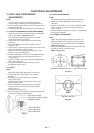
2-4: FOCUS
1.
2.
3.
Receive the monoscope pattern.
Turn the Focus Volume fully counterclockwise once.
Adjust the Focus Volume until picture is distinct.