Slim-Prole TV Mount
QUICK SETUP GUIDE
DX-TVM111
Thank you for choosing the Dynex DX-TVM111.
The DX-TVM111 TV mount is designed to support
a TV weighing up to 30 lbs. (13.6 kg).
Package contents
A Wall plate (1)
B TV bracket (1)
C Locking bar (1)
M4 Bag
D M4 × 12 mm screws (4)
E M4 × 30 mm screws (4)
F M4 spacers (4)
G M4 washers (4)
Lag Bolt Bag
H Concrete wall
anchors (2)
I 1/4 in. × 2½ in.
lag bolts (2)
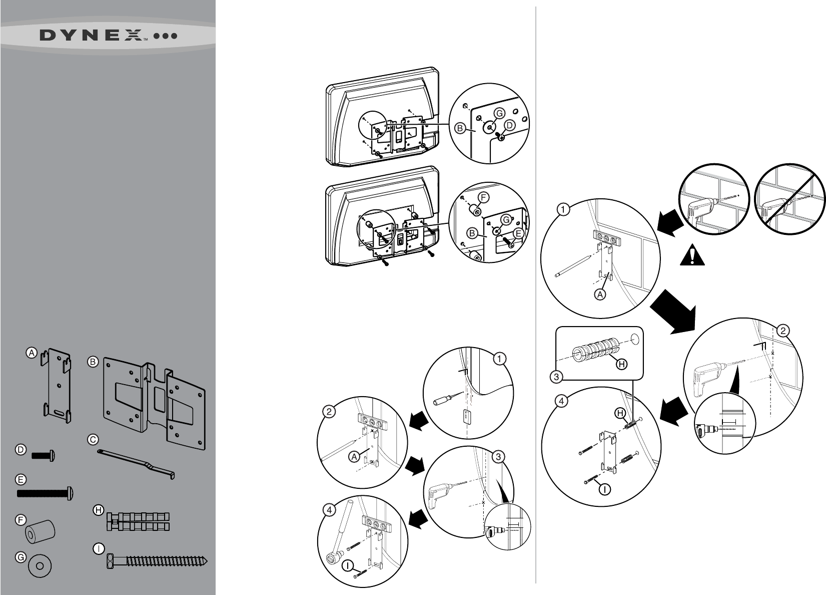
1 Attach the TV bracket
NOTE: Make sure there will be enough space between the back of the TV and
the wall to connect all your cables.
You can use the optional M4 spacers to provide additional space.
Without spacers: Attach the TV bracket (B)
to the back of the TV using
the M4 washers (G)
and the M4 × 12 mm
screws (D).
With spacers: Attach
the TV bracket (B) to the
back of the TV using the
M4 spacers (F), M4
washers (G), and
M4 × 30 mm screws (E).
NOTE: You can mount the
TV vertically or at an angle
(tilt mount). See Step 3
for more information.
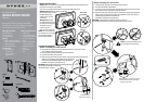
Tools you will need:
• Power drill
• 1/8 in. wood drill bit
• ½ in. masonry drill bit
• Phillips screwdriver
• Level
• Socket wrench with
7/16 in. socket or
adjustable wrench
• Pencil
• Stud nder
• Awl
Lag Bolt Bag
1/4 in. × 2½ in.
M4
Option 2: Installing to a concrete wall
1 Level the wall plate (A) and mark the hole locations.
2 Drill the pilot holes as illustrated.
3 Insert the concrete wall anchors into the pilot holes and make sure that
the anchors (H) are seated ush with the surface.
4 Align the wall plate with the anchors, insert the lag bolts (I) through the
holes in the wall plate, then tighten the lag bolts (I) only until they are
pulled rmly against the wall plate (A).
DO NOT over-tighten the lag bolts (I).
CAUTION: Avoid potential injuries or property damage!
Any material covering the wall must not exceed 5/8 in. (16 mm).
CAUTION: To prevent property damage or personal
injury, never drill into mortar between blocks.
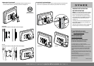
2 Install the wall plate
Option 1: Installing to a wood stud wall
1 Locate the stud. Verify the center of the stud with an awl or thin nail or
use an edge to edge stud nder.
2 Level the wall plate (A) and mark the hole locations.
3 Drill the pilot holes as illustrated.
4 Align the wall plate with the pilot holes, insert the lag bolts (I) through the
holes in the wall plate, then tighten the lag bolts only
until they are pulled rmly against the wall plate (A).
DO NOT over-tighten the lag bolts (I).
CAUTION: Avoid potential injuries or property damage!
Any material covering the wall must
not exceed 5/8 in. (16 mm).
5/8 in.
(<16 mm)**
2.5 in.
(63.5 mm)*
M4 × 12 mm
M4 Bag
M4 × 30 mm
M4
5/8 in.
(<16 mm)
*Drill the pilot hole to a
depth of 2.5 in. (63.5 mm)
2.5 in.
(63.5 mm)*
*Drill the pilot hole to a depth of 2.5 in. (63.5 mm)
**Maximum thickness of any material covering
the stud or concrete surface.
Without spacers
With spacers