


ELAN HOME SYSTEMS
© ELAN Home Systems 2006 • All rights reserved. Page 9
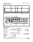
V883 INSTALLATION MANUAL
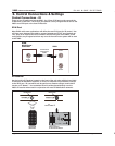
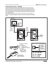
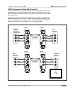
Control Connections - VIA!NET
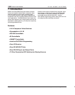
Use the VIA!NET ports when controlling the V883 with ELAN VIA! Touch Panels,
VIA!SC-4 Serial Controller, VIA!2-SS1 System Station and other VIA!NET devices.
Use of this method ensures highly reliable control signal integrity and removes the
possibility of IR signal “collision” whereby simultaneous IR commands cancel each
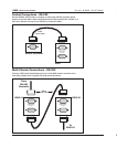
other. The VIA!NET ports on the V883 can be daisy-chained between chassis and
other VIA!NET devices.
Use an ELAN C4545 RJ-45 to RJ-45 interconnect cable to make all VIA!NET con-
nections. If the cable assembly is to be custom made, refer to the pin-out diagram
below.
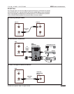
VIA!NET IN
VIA!NET OUT
VIA-NET
PWR
IR
VIA!2-SS1
VIA!NET IN
VIA!NET OUT
V883 #1
V883 #2
To
Additional
VIA!NET
Devices
ELAN
C4545
RJ-45
Connector
ELAN
C4545
RJ-45
Connector
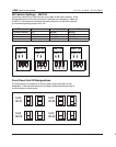
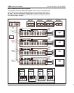
Insert wires in this order:
Blue
White/Blue
Orange - RS-485-
White/Orange - RS-485+
Green
White Green
Brown - GND
White/Brown
RJ-45 Wired to
ELAN Standards
BLUE
WHITE/BLUE
ORANGE
WHITE/ORANGE
GREEN
WHITE/GREEN
BROWN
WHITE/BROWN
1
2
3
4
5
6
7
8
PIN # COLOR CODE
FRONT
CABLE
Standard ELAN RJ-45 Pin-Out
TA B
Pin #3 = RS-485-
Pin #4 = RS485+
Pin #7 = GND