


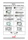

1. Introduction
This document provides the wiring details for the cables used to connect Cello digital
servo drives with the end-user application. The servo drive-side pinouts are provided in
Chapter 3 of the drive’s installation guide.
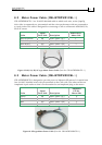
The cables come in two lengths: 2 meters (6 ½ feet) and 5 meters (16 ½ feet). The cable
length is indicated in the cable part number by use of an extended suffix to indicate 5
meter length. For example, cable CBL-CELAUX is a 2 meter cable while
CBL-CELAUX-5 is a 5 meter cable.
CBL-RJ45CAN2, is an exception, it is only 20 cm long.
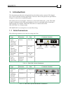
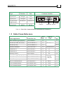
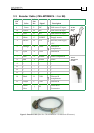
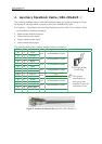
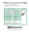
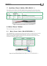
1.1 Cello Connectors
The following connectors are used for wiring the Cello.
Type Function Port Connector Location
5-pin
Pheonix (1
st
two pins)
(provided)
Power VP+, PR
5-pin
Pheonix
(last 3 pins)
(provided)
Motor M1, M2,
M3
3 ground
screws
Ground PE, PE,
PE
2-pin
Pheonix
(provided)
Optional
Back-up
Supply
24 VDC
Table 1-1: The Cello’s Power Connectors
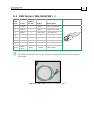
Type Function Port Connector Location
15-pin D-
Sub
Feedback A Feedback A
15-pin D-
Sub (high-
density)
General I/O J1
15-pin D-
Sub (high-
density)
General I/O J2
Table 1-2: The Cello’s I/O and Feedback A Connectors
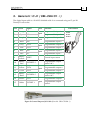
J2: I/O J1: I/O
Feedback A
Optional
Back-up Supply
Ground
Power & Motor
Cello Cable Kits
MAN-CBLKIT-CEL (Ver. 1.0)
1