


–
14
–
EN
1L25
ANT-IN
ANT-OUT
VIDEO OUT
AUDIO OUT
S-VIDEO
OUT
AUDIO
OUT
DIGITAL
AUDIO OUT
COAXIAL
Y
Cb
Cr
L
R
COMPONENT
VIDEO OUT
AUDIO IN
VIDEO IN
DVD/VCR VCR DVD
R
L
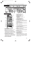
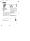
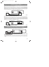
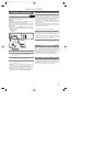
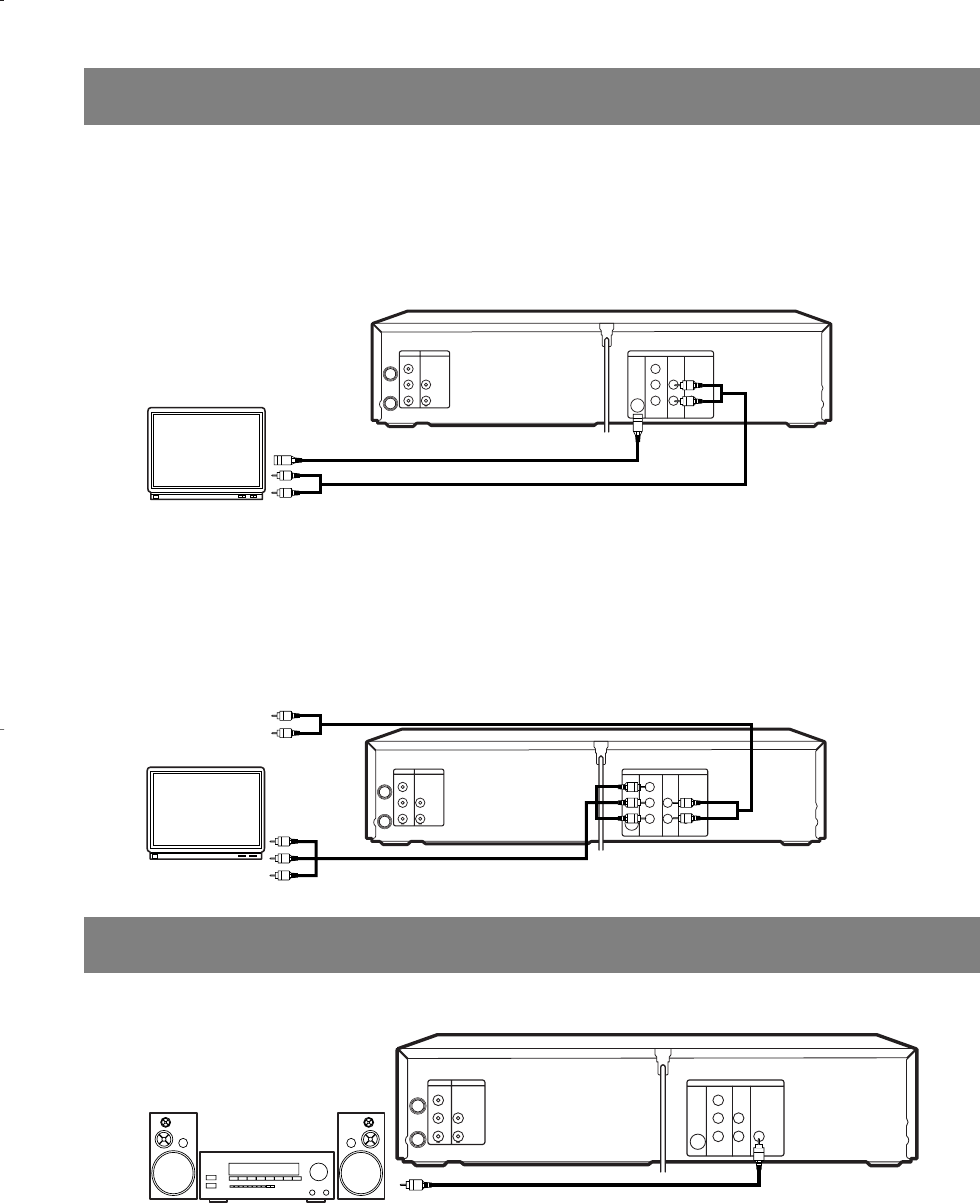
A/V-compatible
or
wide screen TV
To COMPONENT VIDEO
INPUT jacks
To COMPONENT VIDEO
OUT jacks
To Right (red) and Left (white)
AUDIO INPUT jacks
To Right (red) and Left (white)
AUDIO OUTPUT jacks
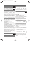
FOR TVs WITH
COMPONENT VIDEO IN JACKS
Use a component video cable (commercially available) in place of the yellow video cable to enjoy higher quality pic-
tures.
The component video connection only supplies video (picture) in the DVD mode of the DVD/VCR COMBINATION
UNITS. Therefore, in order to use the VCR features or view TV channels at the DVD/VCR COMBINATION UNITS,
you still need to either connect the RF coaxial cable between the ANT-OUT jack of the DVD/VCR COMBINATION
UNITS and the TV’s Antenna In jack, or connect the yellow video cable as described earlier (Fig. 1). To connect the
supplied RF cable, see “DVD/VCR TO TV CONNECTION” on page 13.
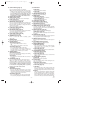
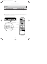
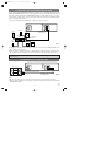
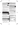
CONNECTING TO AN AMPLIFIER EQUIPPED WITH DIGITAL
INPUT JACKS SUCH AS MD DECK OR DAT DECK
Use an audio coaxial digital cable (commercially available) for the audio connections.
Connecting to an amplifier equipped with digital input jacks such as MD Deck or DAT Deck.
ANT-IN
ANT-OUT
VIDEO OUT
AUDIO OUT
S-VIDEO
OUT
AUDI O
OUT
DIGITAL
AUDIO OUT
COAXIAL
Y
Cb
Cr
L
R
COMPONENT
VIDEO OUT
AUDIO IN
VIDEO IN
DVD/VCR VCR DVD
R
L
To COAXIAL DIGITAL AUDIO INPUT jack
To COAXIAL DIGITAL
AUDIO OUT jack
Amplifier equipped with digital
input jacks, MD deck,
DAT deck, etc.
Notes
¡The audio source on a disc in the 5.1 channel Dolby Digital surround format cannot be recorded as digital
sound by an MD or DAT deck.
¡Set DOLBY DIGITAL to OFF for audio output in the setup mode. Playing a DVD disc using incorrect set-
tings may generate noise distortion, and may also damage the speakers. (See page 29 to set DOLBY DIGITAL
to ON)
[Fig. 4]
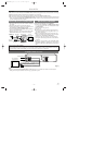
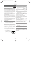
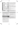
FOR TVs WITH S-VIDEO INPUT JACK
Use an S-Video cable (commercially available) in place of the yellow video cable to enjoy higher quality pic-
tures.
The S-Video connection only supplies video (picture) in the DVD mode of the DVD/VCR COMBINATION
UNITS. Therefore, in order to use the VCR features or view TV channels on the DVD/VCR COMBINATION
UNITS, you still need to either connect the RF cable between the ANT-OUT jack of the DVD/VCR COMBI-
NATION UNITS and the TV’s Antenna In jack, or connect the yellow video cable as described earlier (Fig.1).
To connect the supplied RF cable, see “DVD/VCR TO TV CONNECTION” on page 13.
CONNECTING TO A TV THAT HAS AN S-VIDEO INPUT JACK OR
COMPONENT VIDEO IN JACKS
ANT-IN
ANT-OUT
VIDEO OUT
AUDIO OUT
S-VIDEO
OUT
AUDIO
OUT
DIGITAL
AUDIO OUT
COAXIAL
Y
Cb
Cr
L
R
COMPONENT
VIDEO OUT
AUDIO IN
VIDEO IN
DVD/VCR VCR DVD
R
L
To S-VIDEO OUT jackTo S-VIDEO INPUT jack
To Right (red) and Left (white)
To AUDIO OUT jacksTo AUDIO INPUT jacks
A/V-compatible or
wide screen TV
[Fig. 3]
[Fig. 2]
H9410UD(EN).qx33 03.1.17 6:21 PM Page 14